Valves including one or more flushing features and related assemblies, systems, and methods

a technology of flushing feature and valve body, which is applied in the direction of fluid pressure control, borehole/well accessories, instruments, etc., can solve the problems of increasing the wear and tear of the components of the hydraulic system, increasing maintenance and repair costs, and requiring early replacement of equipmen

Active Publication Date: 2020-05-14
FLOWSERVE PTE LTD
View PDF0 Cites 9 Cited by
  • Summary
  • Abstract
  • Description
  • Claims
  • Application Information

AI Technical Summary

Benefits of technology

[0006]Various embodiments may include a device or system for exchanging pressure between fluids. The device may include a tank and a directional valve device. The tank may include a clean side for receiving a clean fluid at a higher pressure and a dirty side for receiving a downhole fluid (e.g., fracking fluid, drilling fluid) at a lower pressure. At least one port may be positioned proximate to the dirty side of the at least one tank and define a fluid pathway. At least one valve may be disposed along the fluid pathway of the at least one port. The valve may be configured to at least one of enable the downhole fluid to enter the tank or enable the downhole fluid to exit the tank. The valve may includ

Problems solved by technology

These types of fluids may increase the amount of wear on the components of a hydraulic system.
The increased wear may result in increased maintenance and repair costs or require the early replacement of equipment.
For example, abrasive, caustic, or acidic fluid may increase the wear on the internal components of a pump such as an impeller, shaft, vanes, nozzles, etc.
Some pumps are rebuildable an

Method used


Image

  • Valves including one or more flushing features and related assemblies, systems, and methods
  • Valves including one or more flushing features and related assemblies, systems, and methods
  • Valves including one or more flushing features and related assemblies, systems, and methods

Examples


Embodiment Construction

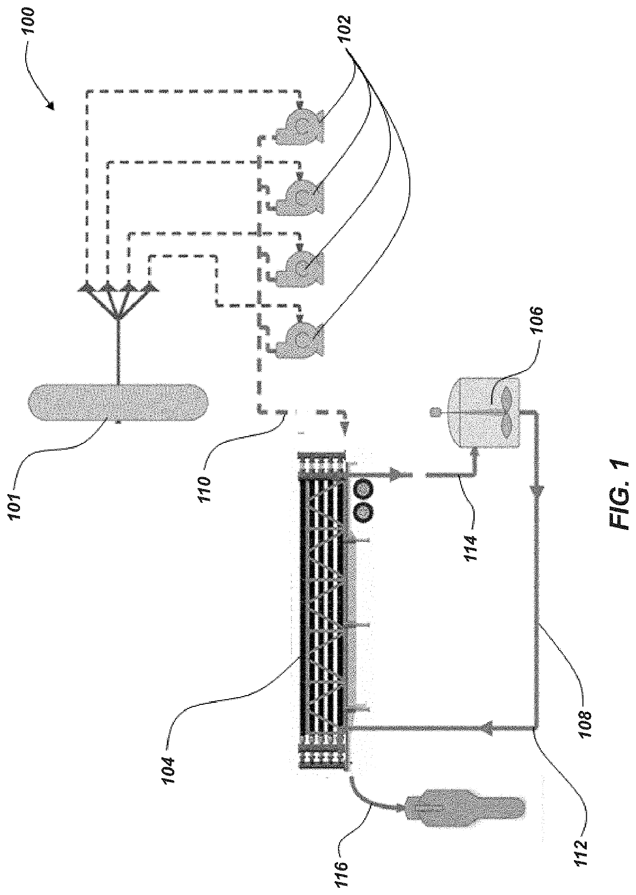
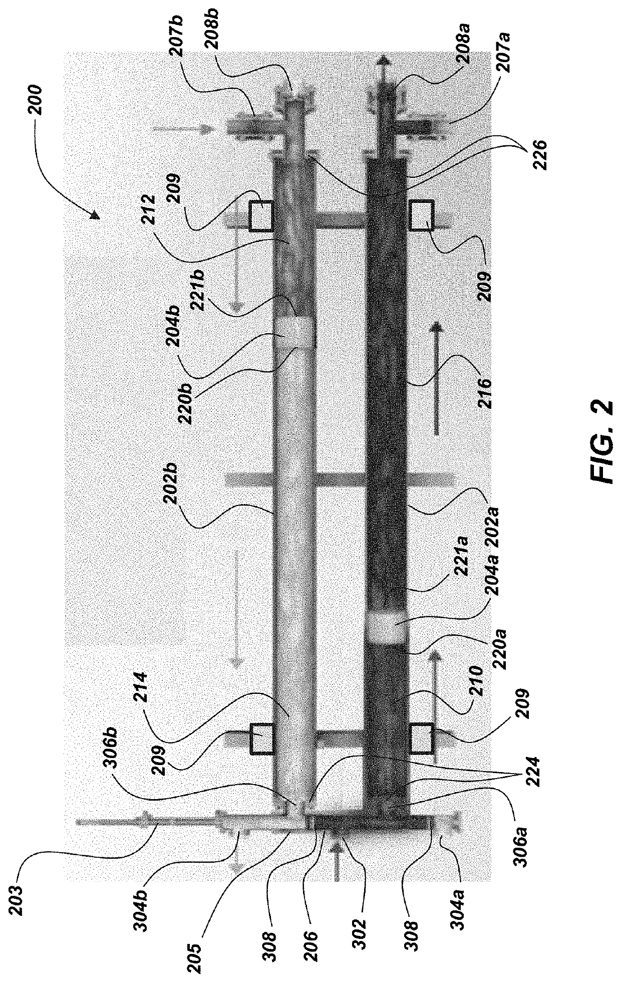
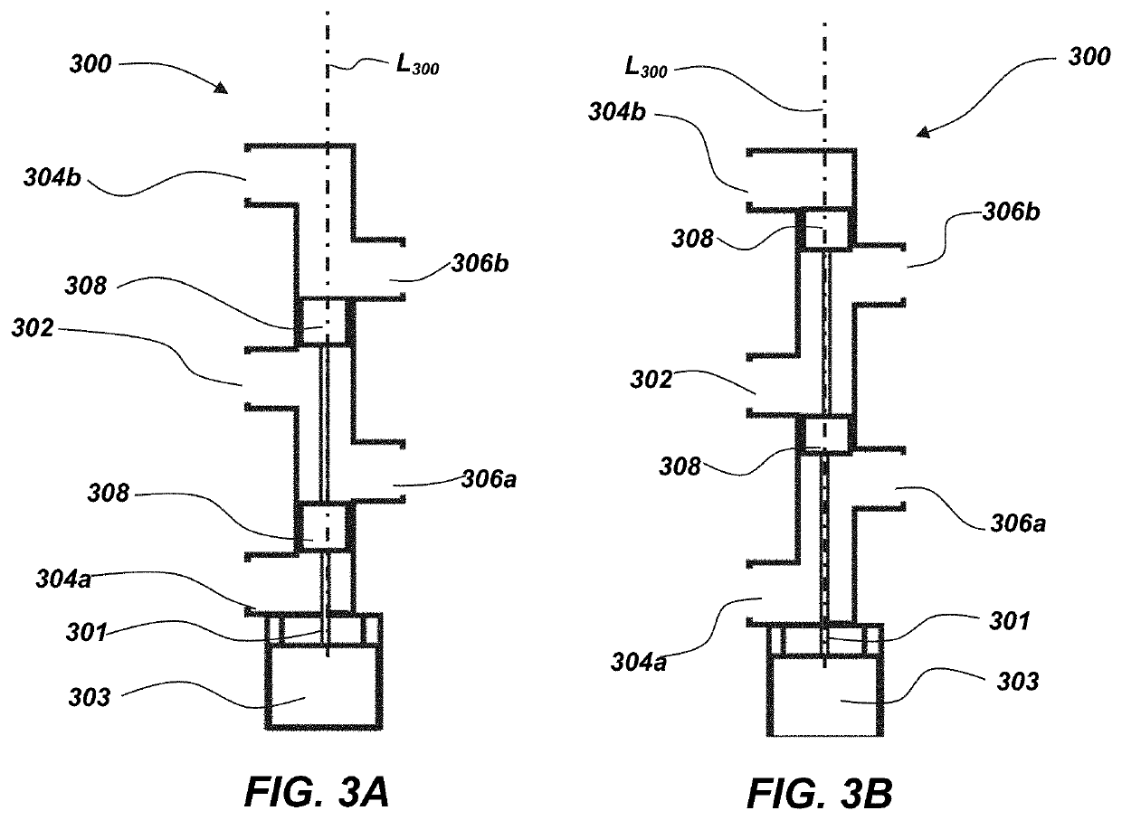
[0018]The illustrations presented herein are not meant to be actual views of any particular fluid exchanger or component thereof, but are merely idealized representations employed to describe illustrative embodiments. The drawings are not necessarily to scale. Elements common between figures may retain the same numerical designation.

[0019]As used herein, relational terms, such as “first,”“second,”“top,”“bottom,” etc., are generally used for clarity and convenience in understanding the disclosure and accompanying drawings and do not connote or depend on any specific preference, orientation, or order, except where the context clearly indicates otherwise.

[0020]As used herein, the term “and / or” means and includes any and all combinations of one or more of the associated listed items.

[0021]As used herein, the terms “vertical” and “lateral” refer to the orientations as depicted in the figures.

[0022]As used herein, the term “substantially” or “about” in reference to a given parameter means...


PUM


Abstract

Valve and related assemblies, systems, and methods may include a self-cleaning feature that may be configured to at least partially displace material from a portion of the valve. Such valves may be utilized in a pressure exchanger.

Description

CROSS-REFERENCE TO RELATED APPLICATION[0001]This application claims the benefit under 35 U.S.C. § 119(e) of U.S. Provisional Patent Application Ser. No. 62 / 758,340, filed Nov. 9, 2018, for “Valves Including One or More Flushing Features and Related Assemblies, Systems, and Methods,” the disclosure of which is hereby incorporated herein in its entirety by this reference.TECHNICAL FIELD[0002]Embodiments of the disclosure relate generally to valves including one or more flushing features. More particularly, embodiments of the disclosure relate to valves one or more flushing features for removing debris or other object from the valve and to related assemblies and to related methods. In some instances, such valves may be utilized in fluid exchange devices for one or more of exchanging properties (e.g., pressure) between fluids and systems and methods.BACKGROUND[0003]Industrial processes often involve hydraulic systems including pumps, valves, impellers, etc. Pumps, valves, and impellers ...

Claims


Application Information

Patent Timeline
IPC IPC(8): F16K51/00G05D16/00B08B5/02B08B9/032
CPCB08B2209/032F16K11/07G05D16/028B08B9/0328B08B5/02F16K15/02F16K51/00B08B9/00F16K15/023F16K25/02E21B43/2607
Inventor CHRISTIAN, CINNAMONSCHAPPERT, STEPHENDREISS, ANDREASNITZ, TIMO'SULLIVAN, MARK
Owner FLOWSERVE PTE LTD
Why Eureka
Try Eureka