
System and method for dynamic process modeling, error correction and control of a reheat furnace

a dynamic process and reheat furnace technology, applied in the direction of furnaces, lighting and heating apparatus, control devices, etc., can solve the problems of increasing rolling power, reducing the efficiency of reheat furnaces, so as to achieve the effect of reducing fuel us

Pending Publication Date: 2020-05-21
GRIFFIN OPEN SYST LLC
View PDF1 Cites 1 Cited by
  • Summary
  • Abstract
  • Description
  • Claims
  • Application Information

AI Technical Summary

Benefits of technology

This approach ensures that slabs are discharged at appropriate temperatures, minimizing fuel use and reducing rejection rates, while allowing for real-time configuration and programming changes without interrupting the process, thereby optimizing heat rate and quality control.

Problems solved by technology

If it is too hot, the steel may have excessive slagging or surface melting; if too cold, increased rolling power is required, and slabs may be rejected as the desired metallurgical properties are not obtained.
Most reheat furnaces, however, are not equipped to reliably measure slab temperatures inside the furnace.
Thus, it is possible for conflicting temperature patterns to be produced, which can result in wasted heat and slab rejects.
One complication that arises when operating a reheat furnace is variability in the operating conditions of the rolling mill operations and other facets (e.g. slab loading, scheduling) of the production line which affect the rate at which slabs can be extracted from the furnace(s).
The method can also incorporate the effects of other production delays, such as unexpected rolling suspensions (holds) of varying duration.
Furthermore, this method is not ideal for fuel savings in the case of long holds, and does not account for holds of unknown duration.
A second complication arises when furnaces are charged with a mix of slabs, which can vary in size, weight, composition, and temperature requirement.
Temperatures are then controlled to adequately heat the virtual slab while minimizing fuel use, although the patent does not describe how to select those temperatures nor how to correct for errors in the virtual slab temperature estimates.
Further complications include variable burner performance and air and fuel mix distribution.
Slab placement within the furnace affects the side to side temperature profile of a slab, which will result in poor head to tail temperature profiles on furnace exit, even when the average enthalpy and heat content of the slab are correct.
A limitation in U.S. Pat. Nos. 4,255,133 and 4,501,552 is the method of selecting temperatures are based on a heat balance analysis of the entire furnace, and accuracy of these methods requires precisely knowing several coefficients describing the furnace's thermal characteristics, such as how much heat is escapes through exhaust and other losses (stack losses, heat of input gas etc.).
The virtual slab method described in U.S. Pat. No. 5,006,061 addresses heating a mix of material, but does not give guidance on the actual temperature selection.
Additional challenges are centered around knowing the heat input, where inaccuracies in the measurement of air and gas flows impact the energy input, and measurement of non-combusted gas (CH4) and other partial reactions such as CO are not measured or only measured sparingly and are not fully representative of the actual heat released.
A compounding problem is that the actual temperature measurement of the slab surface will have its own non-reproducible errors, which may arise from gravel on the surface of a slab, slag build-up on the surface, debris on the sensor, etc.
In the operation of a reheat furnace, a substantial amount of the steel in the slab is lost due to surface oxidization while in the furnace.
Excess combustion air also results in potential cooling of the slabs, and requires extra fuel just to heat the additional air, and extra electricity to power the fans providing the air.
However, this does not guarantee customizability of the underlying control by users, especially users without programming expertise.

Method used


Image

  • System and method for dynamic process modeling, error correction and control of a reheat furnace
  • System and method for dynamic process modeling, error correction and control of a reheat furnace
  • System and method for dynamic process modeling, error correction and control of a reheat furnace

Examples


Embodiment Construction

[0035]The present invention provides a system and method for controlling the temperature setpoints in a large scale steel reheat furnace such that a wide variety (even random) mixture of slabs with different compositions, sizes, initial temperatures, temperature requirements, and anticipated residence times are all discharged at an appropriate temperature with emphasis on ensuring that no slab is insufficiently heated per rolling and quality requirements. This is accomplished with minimized fuel use per ton of steel produced. The present invention combines this system with a graphical user interface where real-time configuration and programming changes can be made without interrupting the process or process control.

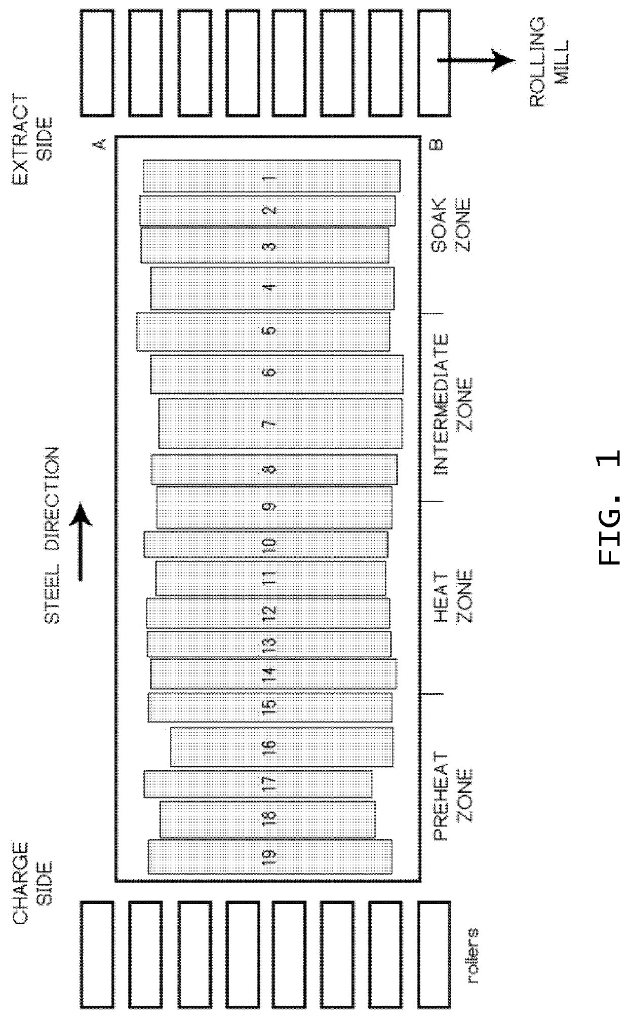
[0036]An example of a steel reheat furnace is shown in FIG. 1. The view is top down; slabs are charged at the left side, traverse rightward through the furnace, and are extracted at the right end, where they proceed on rollers to be milled. Such furnaces are divided into ...


PUM


Abstract

A system and method for controlling the temperature setpoints in a furnace such that a random mixture of slabs with different compositions, sizes, initial temperatures, temperature requirements, and anticipated residence times are all discharged at an appropriate temperature, with emphasis upon ensuring that no slab is insufficiently heated (rejected) per rolling and quality requirements. This is to be accomplished with minimized fuel use. This system can be implemented in a graphical programming environment, where real-time tuning, configuration, logic changes, model replacement, model retraining and other programming changes can be made without interruption of control.

Description

BACKGROUNDField of the Invention[0001]The present invention relates generally to controlling large-scale reheat furnaces, and in particular to a system and method for controlling temperature setpoints and regulating slab extraction from a multi-zone steel reheat furnace.Description of the Prior Art[0002]Steel reheat furnaces, particularly walking beam furnaces, are typically divided into multiple zones along their length where the temperatures in each zone are controlled by one or more burners located in the zones. When multiple burners exist in a given zone, it is possible that fuel flow through each burner may be controlled individually giving independent side to side and / or top to bottom temperature control. Steel slabs are loaded from a charge side and traverse through the furnace over a period of time until they are extracted at which point they enter the rolling mill. Heat rate is the average amount of heat available from the heating source (e.g. natural gas) consumed per ton ...

Claims


Application Information

Patent Timeline
Patent Type & Authority Applications(United States)
IPC IPC(8): F27D19/00
CPCF27D2019/0003F27D2019/0065F27D19/00
Inventor VESEL, RICHARD W.ALAGARSAMY, SIVASHANMUGAMRADL, BRAD J.
Owner GRIFFIN OPEN SYST LLC
Learn More