Micro fluid actuator

a micro-fluid actuator and actuator technology, applied in the field of actuators, can solve the problems of insufficient flow rate transmission, and achieve the effect of increasing the fluid compression ratio and too small piezoelectric layer displacemen

Active Publication Date: 2020-05-28
MICROJET TECH
View PDF1 Cites 3 Cited by
  • Summary
  • Abstract
  • Description
  • Claims
  • Application Information

AI Technical Summary

Benefits of technology

[0005]The object of the present disclosure is to provide a micro fluid actuator manufactured by micro-electromechanical system process and capable of transporting fluid. The micro fluid actuator of the present disclosure is manufactured by semiconductor thin film process, therefore, the depth of a storage chamber of the micro fluid actuator can be designed to be very shallow, so as to increase the fluid compression ratio at the time of actuation and to compensate for the disadvantage that the displacement of the piezoelectric layer is too small.

Problems solved by technology

It is obviously that the conventional fluid transportation devices gradually tend to miniaturize the structure and maximize the flow rate thereof.
However, when the conventional micro fluid actuator is actuated, the displacement of the piezoelectric layer is too small so that the flow rate transmitted is insufficient.

Method used


Image

  • Micro fluid actuator
  • Micro fluid actuator
  • Micro fluid actuator

Examples


Embodiment Construction

[0014]The present disclosure will now be described more specifically with reference to the following embodiments. It is to be noted that the following descriptions of preferred embodiments of this disclosure are presented herein for purpose of illustration and description only. It is not intended to be exhaustive or to be limited to the precise form disclosed.

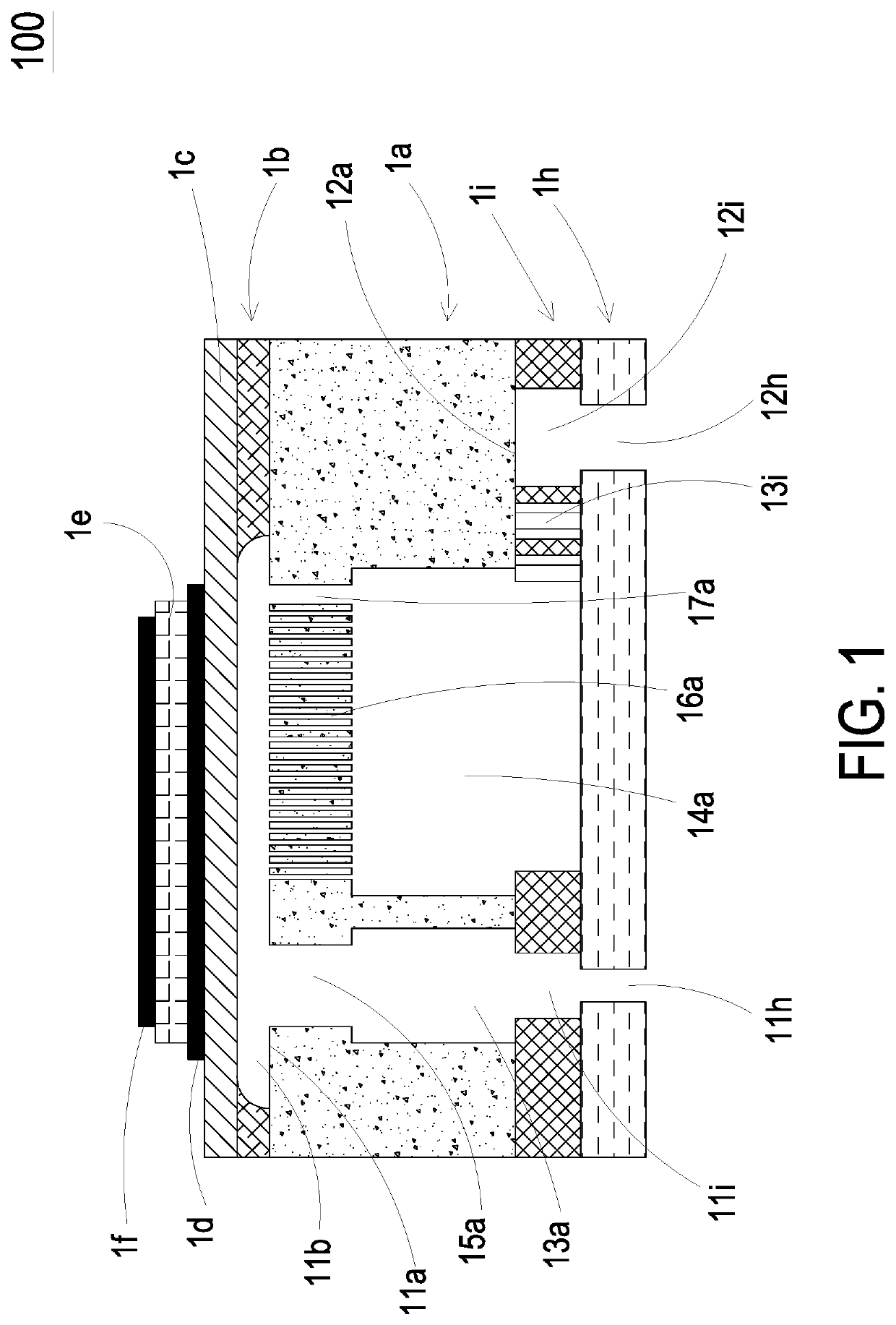
[0015]Please refer to FIG. 1, the present disclosure provides a micro fluid actuator 100, which includes at least one substrate 1b, at least one chamber layer 1b, at least one vibration layer 1c, at least one lower electrode layer 1d, at least one piezoelectric actuation layer 1e, at least one upper electrode layer 1f, at least one orifice layer 1h and at least one flow channel layer 1i. The numbers of the substrate 1a, the chamber layer 1b, the vibration layer 1c, the lower electrode layer 1d, the piezoelectric actuation layer 1e, the upper electrode layer 1f, the orifice layer 1h and the flow channel layer 1i are exemplified ...


PUM

PropertyMeasurementUnit
diametersaaaaaaaaaa
aspect ratio d/saaaaaaaaaa
thicknessaaaaaaaaaa

Abstract

A micro fluid actuator includes an orifice layer, a flow channel layer, a substrate, a chamber layer, a vibration layer, a lower electrode layer, a piezoelectric actuation layer and an upper electrode layer, which are stacked sequentially. An outflow aperture, a plurality of first inflow apertures and a second inflow aperture are formed in the substrate by an etching process. A storage chamber is formed in the chamber layer by the etching process. An outflow opening and an inflow opening are formed in the orifice layer by the etching process. An outflow channel, an inflow channel and a plurality of columnar structures are formed in the flow channel layer by a lithography process. By providing driving power which have different phases to the upper electrode layer and the lower electrode layer, the vibration layer is driven to displace in a reciprocating manner, so as to achieve fluid transportation.

Description

FIELD OF THE DISCLOSURE[0001]The present disclosure relates to an actuator, and more particularly to a micro fluid actuator manufactured by micro-electromechanical semiconductor thin film process.BACKGROUND OF THE DISCLOSURE[0002]Currently, in all fields, such as pharmaceutical industries, computer techniques, printing industries and energy industries, products are developed toward elaboration and miniaturization. The fluid transportation devices that are comprised in, for example, micro pumps, micro atomizers, print heads and industrial printing devices are important components.[0003]With the rapid advance of technology, the application of the fluid transportation devices tends to be more and more diversified. For example, the industrial applications, the biomedical applications, the healthcare, the electronic cooling and so on, even the wearable devices, which are popular recently, the fluid transportation device are utilized therein. It is obviously that the conventional fluid tr...

Claims


Application Information

Patent Timeline
Patent Type & Authority Applications(United States)
IPC IPC(8): F16K99/00B81C1/00
CPCF16K99/0048B81C1/00166B81C1/00031B81B2201/032B81B2201/036B81B2201/10B81C1/00182B81B2203/0127B81B2203/0315F04B43/046B81B3/0021
Inventor MOU, HAO-JANYU, RONG-HOCHANG, CHENG-MINGTAI, HSIEN-CHUNGLIAO, WEN-HSIUNGHUANG, CHI-FENGHAN, YUNG-LUNGCHEN, HSUAN-KAI
Owner MICROJET TECH
Why Eureka
Try Eureka