
High-strength spring steel, method for producing high-strength spring, and high-strength spring

A manufacturing method, high-strength technology, applied to high-strength spring steel, high-strength spring. field, which can solve problems such as high cost, uneven and unclear distribution of Ni production countries or regions

Active Publication Date: 2013-07-10
NHK SPRING CO LTD
View PDF4 Cites 14 Cited by
  • Summary
  • Abstract
  • Description
  • Claims
  • Application Information

AI Technical Summary

Problems solved by technology

As a method for improving such corrosion resistance and delayed fracture resistance, for example, high-strength steel for coil springs (hereinafter referred to as conventional high-strength steel) described in Patent Document 1, which contains expensive alloy elements such as Ni, Cr, Mo, and V, etc. Cr steel) As the use environment becomes harsher, the amount of alloying elements added increases, so the cost of raw materials increases
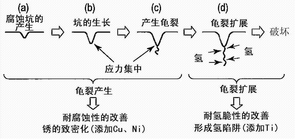
In addition, the addition of a large amount of Cr is not only costly, but also leads to instability of the raw material supply system, and there is also a physical negative effect of making the shape of the corrosion pit an acute angle.
That is, the presence of Cr has a positive effect on general corrosion, but it has a negative effect on corrosion pits (pitting corrosion). As the amount of addition, it is not clear which value is the optimal value of Cr amount
[0004] In addition, although Ni has the effect of improving corrosion resistance and increasing the amorphous composition of rust to reduce the aspect ratio of corrosion pits, it not only leads to a large increase in cost, but also uneven distribution of countries or regions where Ni is produced , the raw material supply system is unstable

Method used


Image

  • High-strength spring steel, method for producing high-strength spring, and high-strength spring
  • High-strength spring steel, method for producing high-strength spring, and high-strength spring
  • High-strength spring steel, method for producing high-strength spring, and high-strength spring

Examples


Embodiment

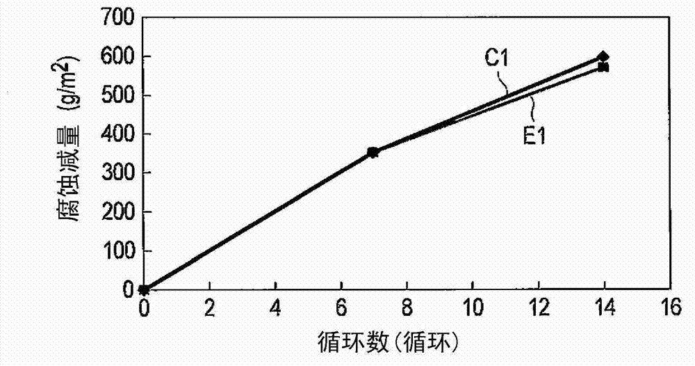
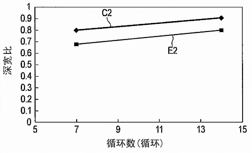
[0151] Hereinafter, examples will be given with reference to the drawings and tables, and the present invention will be described in detail while being compared with comparative examples and reference examples. However, the present invention is not limited to the following examples, and can be implemented with various changes within a range that can suit the subject and purpose of the present invention.

[0152] Comparative examples 1 to 4 (steel grades A to D), Examples 1 to 7 (steel grades E to K) and reference examples 1 and 2 (steel grades L, M) using the compositions shown in Table 4 and Table 5 The hot-rolled coil springs and cold-rolled coil springs shown in Table 6 were manufactured for each steel type. Here, steel types A to D of comparative examples are conventional steels that reproduce the composition ratios described in Patent Document 2. In addition, the steel types L and M of the reference example are conventional high-Cr steels that reproduce the composition r...


PUM

PropertyMeasurementUnit
phase transition temperatureaaaaaaaaaa
grain sizeaaaaaaaaaa

Abstract

This high-strength spring steel is characterized by: containing, by mass%, 0.38-0.44% of C, 2.00-2.30% of Si, 0.79-1.25% of Mn, 0.10-0.43% of Cr, 0.15-0.35% of Ni, 0.15-0.35% of Cu, 0.05-0.13% of Ti, no greater than 0.02% of P, no greater than 0.02% of S, 0.003-0.10% of Al, 0.002-0.012% of N, no greater than 0.0002% of O, the remainder comprising iron and unavoidable impurities; the AC3 transformation point, which is an index for decarbonizing performance determined from the belowmentioned formula (1), being in the range of 859-885 DEG C inclusive; the maximum quenching diameter (DI), which is an index for quenching performance determined from the belowmentioned formula (2), being in the range of 70-238 mm inclusive; and the tempered hardness (HRC), which is an index for spring performance determined from the belowmentioned formula (3), being in the range of 50-55 inclusive. Ac3=910-203vC -15.2Ni+44.7Si+104V+31.5Mo+13.1W ...(1); DI=DOfSifMnfPfSfCufNifCr ...(2); and HRC=38.99 + 17.48 C + 2.55 Si - 2.28 Ni + 2.37 Cr + 8.04 Ti ...(3); where D0=8.65vC, fSi=1 + 0.64 %Si, fMn=1 + 4.10 %Mn, fP=1 + 2.83 %P, fS=1 - 0.62 %S, fCu=1 + 0.27 %Cu, fNi=1 + 0.52 %Ni, and fCr=1 + 2.33 %Cr.

Description

technical field [0001] The present invention relates to a high-strength spring steel used for spring parts for vehicles and the like, a method for manufacturing a high-strength spring, and a high-strength spring manufactured by the method. Background technique [0002] In response to environmental assessment for the purpose of preventing global warming, in the automotive industry, weight reduction of vehicle bodies is desired in order to limit carbon dioxide emissions. One of the ways to realize the desire to reduce the weight of the vehicle body is to increase the strength of the coil springs used to support the vehicle body. In addition, on the other hand, coil springs for vehicle body support are required to be durable because they are exposed to severe corrosion environments. [0003] In order to ensure the durability of the coil spring in a corrosive environment, research and development have been carried out to improve the corrosion resistance of the material by addin...

Claims


Application Information

Patent Timeline
Patent Type & Authority Applications(China)
IPC IPC(8): C22C38/50C21D7/06C21D9/02F16F1/06
CPCC21D7/06C21D8/06C21D8/065C21D9/02C22C38/001C22C38/04C22C38/06C22C38/34C22C38/42C22C38/50C21D9/52C22C38/20C22C38/28C22C38/46C22C38/02F16F1/06F16F1/02F16F1/021
Inventor 冈田秀树丹下彰丹后公一住吉功
Owner NHK SPRING CO LTD
Learn More