
Emission protection device and method for operating a load

Active Publication Date: 2020-05-28
ROBERT BOSCH GMBH
View PDF0 Cites 1 Cited by
  • Summary
  • Abstract
  • Description
  • Claims
  • Application Information

AI Technical Summary

Benefits of technology

The present invention provides options for reducing or eliminating electromagnetic interference, which can be generated during the operation of a load. The invention uses an electromagnetic field to create a counter field that reduces or compensates for the interference. This technology aims to improve protection from electromagnetic interference and prevent interference from affecting a signal reception. The invention also includes alternatives for cost-effective signal generation.

Problems solved by technology

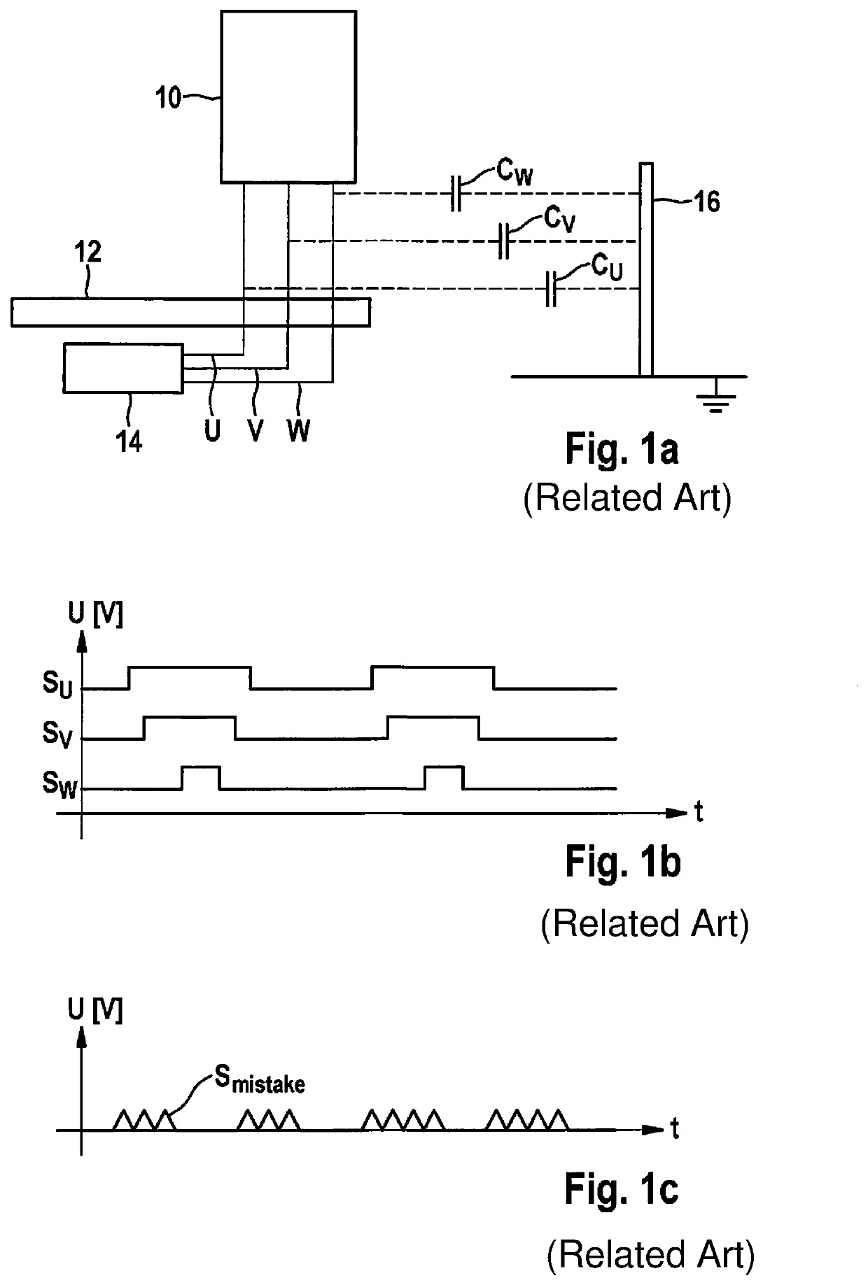
The activation, switching, and / or energizing of load 10 using electrical signals Su, Sv, and Sw generates an undesirable electromagnetic interference field, however.

Method used


Image

  • Emission protection device and method for operating a load
  • Emission protection device and method for operating a load
  • Emission protection device and method for operating a load

Examples


Embodiment Construction

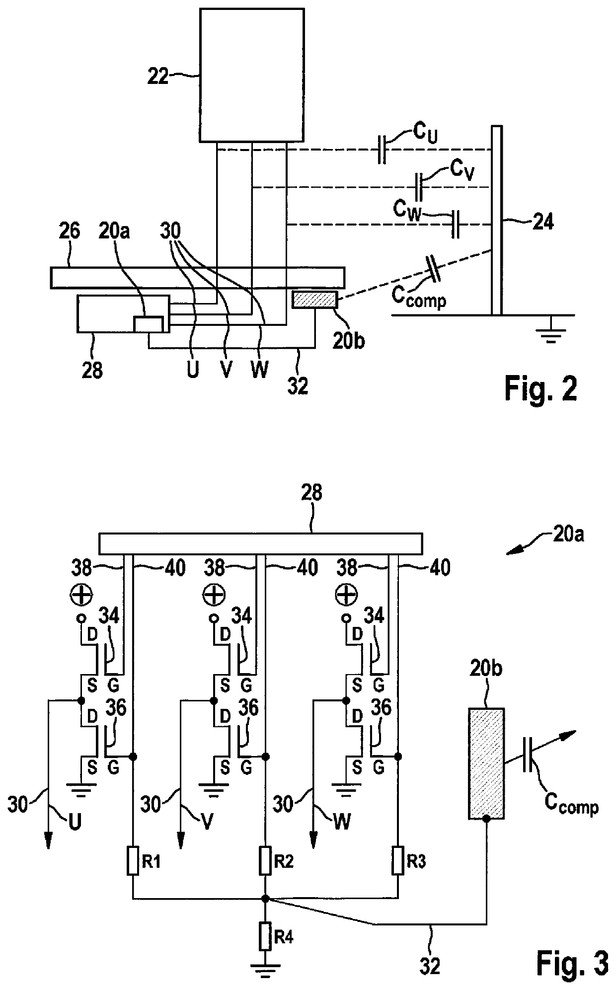
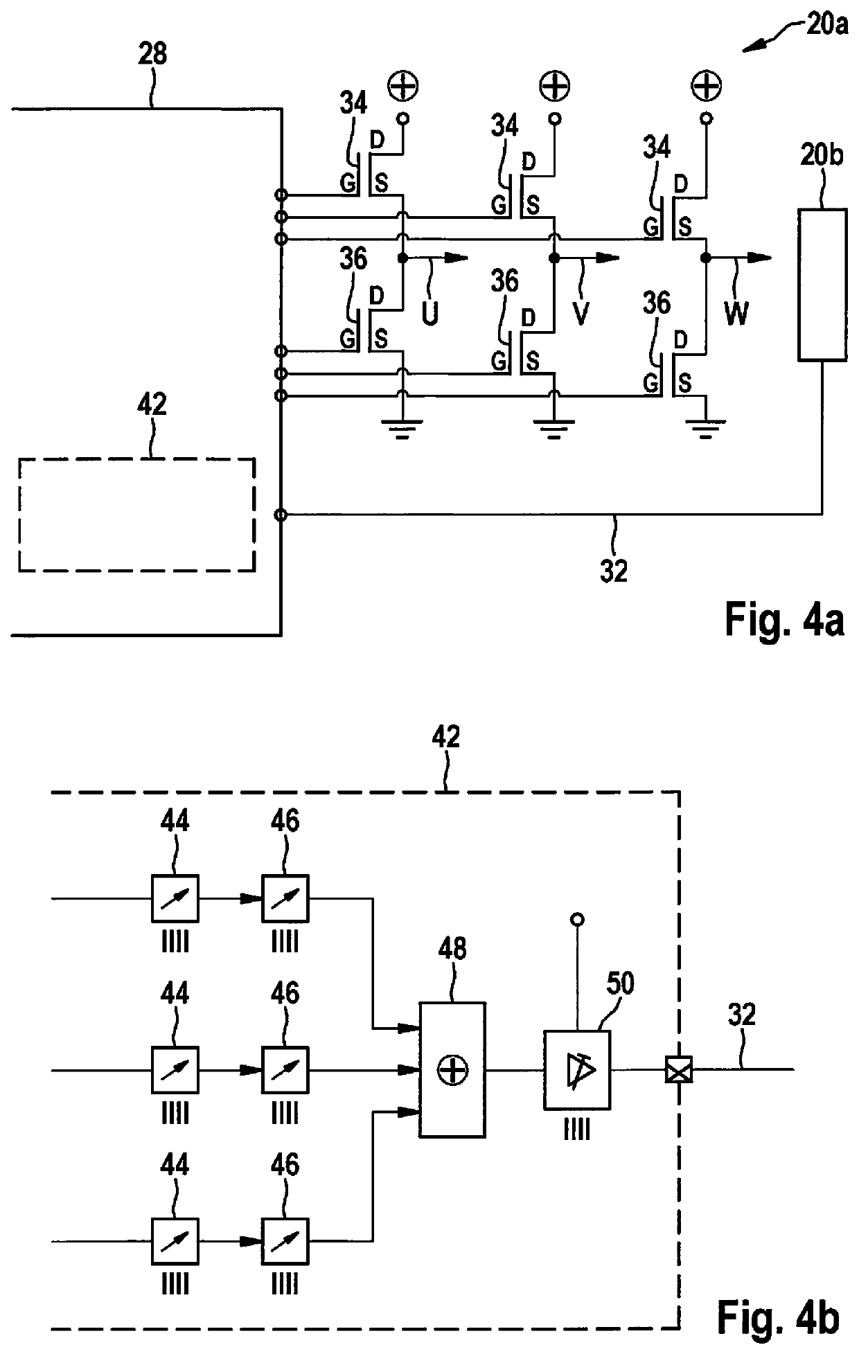
[0021]FIG. 2 shows a schematic view of a first specific embodiment of the emission protection device.

[0022]Emission protection device 20a and 20b, which is schematically shown in FIG. 2, is configured to interact with a motor 22 as a load 22. For example, motor 22 is a brushless DC motor 22 (BLDC), in particular a brushless three-phase motor 22, which is configured for a clocked motor activation. However, it is to be noted that a usability of emission protection device 20a and 20b explained hereafter is not limited to a configuration of load 22 as a motor 22. For example, emission protection device 20a and 20b may also be used for a load 22 which is a valve, a light-emitting unit (for example, a device having at least one light-emitting diode), and / or an electronic device, such as a domestic appliance, a material processing device (for example, an electrical saw), and / or a high-power device, in particular. Emission protection device 20a and 20b is thus versatile. Moreover, it is to ...


PUM


Abstract

An emission protection device including a signal generating unit to generate, for at least one electrical signal relayed by at least one conductor to a load, with which the load is switchable and / or energize-able, at least one electrical output signal, which is phase-shifted by 180° compared to the at least one electrical signal, and an emitting structure, which is connected to the signal generating unit so that the emitting structure is excitable with the at least one electrical output signal to emit an electromagnetic field. Also described is a bridge driver for a load, a controller for a load, and a load, as well as a method for operating a load by switching and / or energizing the load with the at least one electrical signal, generating the at least one electrical output signal, and exciting the emitting structure using the at least one electrical output signal to emit an electromagnetic field.

Description

FIELD OF THE INVENTION[0001]The present invention relates to an emission protection device. The present invention also relates to a bridge driver for a load, a controller for a load, and a load. Furthermore, the present invention relates to a method for operating a load.BACKGROUND INFORMATION[0002]FIGS. 1a through 1c show a schematic view of a conventional load and coordinate systems to explain a standard procedure for operating a load according to the related art.[0003]Conventional load 10 schematically shown in FIG. 1a is operated with the aid of a controller 14 situated on a circuit board 12. For this purpose, load 10 is connected via three phase lines U, V, and W to controller 14. Electrical signals Su, Sv, and Sw, which are relayed by phase lines U, V, and W to load 10 and with the aid of which load 10 is switched and / or energized, are shown in the coordinate system in FIG. 1b, an abscissa being a time axis t and an ordinate indicating a voltage U (in volts). (A signal amplitud...

Claims


Application Information

Patent Timeline
IPC IPC(8): H01F7/06B60R16/02
CPCH01F7/064B60R16/02H04B2215/00H04B15/02
Inventor HUEBL, JOCHENKRALICEK, PETERKUBACH, MICHAEL
Owner ROBERT BOSCH GMBH
Learn More