Method and device for at least partly, preferably completely, determining the external and internal geometry of a component with at least one cavity

a technology of external and internal geometry and a cavity, which is applied in the direction of manufacturing tools, instruments, and using reradiation, etc., can solve the problems of loss of signal sensitivity, restricted resolution, and falling with increasing thickness

a technology of external and internal geometry and a cavity, which is applied in the direction of manufacturing tools, instruments, and using reradiation, etc., can solve the problems of loss of signal sensitivity, restricted resolution, and falling with increasing thickness

US20200173936A1Inactive Publication Date: 2020-06-04SIEMENS ENERGY GLOBAL GMBH & CO KG

Image

  • Method and device for at least partly, preferably completely, determining the external and internal geometry of a component with at least one cavity
  • Method and device for at least partly, preferably completely, determining the external and internal geometry of a component with at least one cavity

Examples


Embodiment Construction

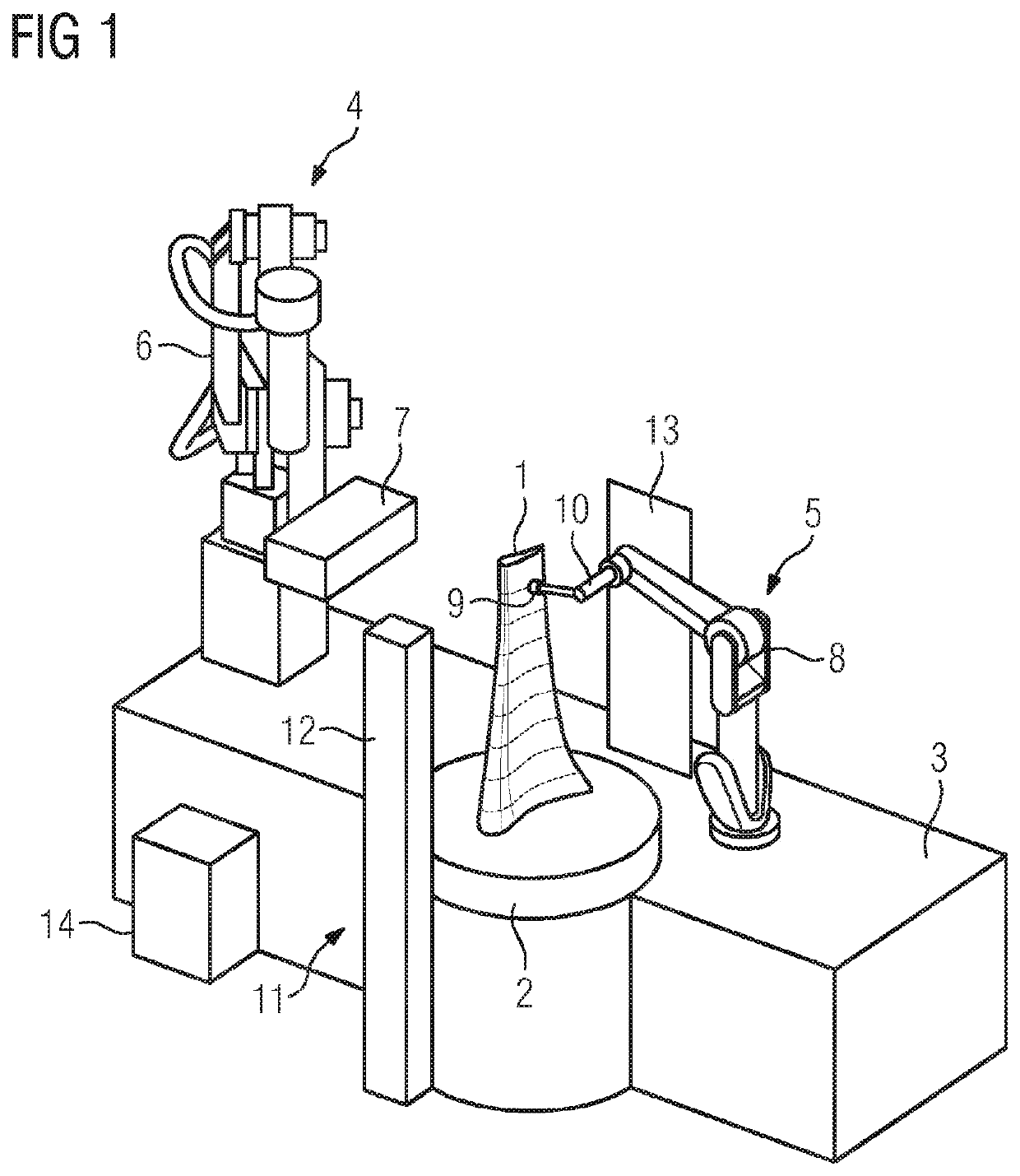
[0039]FIG. 1 shows a purely schematic illustration of a device according to embodiments of the invention for determining the external and internal geometry of a turbine blade 1 with a plurality of internal cooling ducts.

[0040]The device comprises a receptacle for a turbine blade 1 to be surveyed which forms a holder for a turbine blade 1, not recognizable in the figure for reasons of a simplified illustration, which is fastened to the upper side of a turntable 2 arranged on a plinth 3 of the device. A turbine blade 1 with a plurality of internally located cooling ducts is shown in FIG. 1 in a state in which it is held at the turntable 2.

[0041]The device further comprises a 3D scan apparatus 4 and an ultrasonic apparatus 5 that are arranged on the plinth 3 respectively on the left and right of the turntable 2 in FIG. 1.

[0042]The 3D scan apparatus 4 comprises a robot 6, designed in the present case as an articulated-arm robot, and a 3D scan measuring head 7 which is fastened at the fr...


PUM

PropertyMeasurementUnit
thicknessaaaaaaaaaa
thicknessaaaaaaaaaa
thicknessaaaaaaaaaa

Abstract

Provided is a method for determining the external and internal geometry of a component with at least one cavity, wherein a component to be measured is provided with at least one cavity, the external geometry of the component is determined by carrying out a 3D scan, the wall thickness of at least one section of the component is determined using ultrasound, the internal and external component geometry of at least one section of the component in particular is determined using x-ray computer tomography, and the data obtained by means of the 3D scan, the ultrasound wall thickness measurement, and in particular the x-ray computer tomography is combined, wherein the internal geometry of the component in the region of the at least one section measured using ultrasound is reconstructed from the external geometry data of the 3D scan and the data of the ultrasound wall thickness measurement.

Description

CROSS-REFERENCE TO RELATED APPLICATIONS[0001]This application claims priority to PCT Application No. PCT / EP2018 / 2018 / 059551, having a filing date of Apr. 13, 2018, which is based off of DE Application No. 10 2017 208 106.6, having a filing date of May 15, 2017, the entire contents both of which are hereby incorporated by reference.FIELD OF TECHNOLOGY[0002]The following relates to a method and a device for at least partly, completely, determining the external and internal geometry of a component with at least one cavity.BACKGROUND[0003]Various methods are available at present for metrologically determining the external three-dimensional geometry of a component. It is possible, for example, to carry out a 3D scan in which the component surface is sampled with light. Structured light or laser that is aimed at the component to be surveyed can then be used here. Points on the component surface can be deduced from a proportion of the light reflected from the component surface, in particul...

Claims


Application Information

Patent Timeline
04 Jun 2020
Publication
US20200173936A1
IPC
G01N23/046; G01S15/89; B25J9/16; G01B17/02; F01D5/18
CPC
G01B17/02; G01S15/8993; G01N2223/419; G01N23/046; B25J9/1694; F01D5/18; G01B15/045; G01B11/25
Inventors
VÖHRINGER, DANIEL; KAMENZKY, SUSANNE