Fatigue Life Estimation Method and System

Active Publication Date: 2012-03-01
SIEMENS ENERGY GLOBAL GMBH & CO KG
View PDF2 Cites 20 Cited by
  • Summary
  • Abstract
  • Description
  • Claims
  • Application Information

AI Technical Summary

Benefits of technology

[0016]In an exemplary embodiment, said component is a gas turbine component. The present invention is particularly useful for g

Problems solved by technology

Depending on the underlying probability distribution functions as well as the curve parameters that are to be determined, the “

Method used


Image

  • Fatigue Life Estimation Method and System
  • Fatigue Life Estimation Method and System
  • Fatigue Life Estimation Method and System

Examples


Embodiment Construction

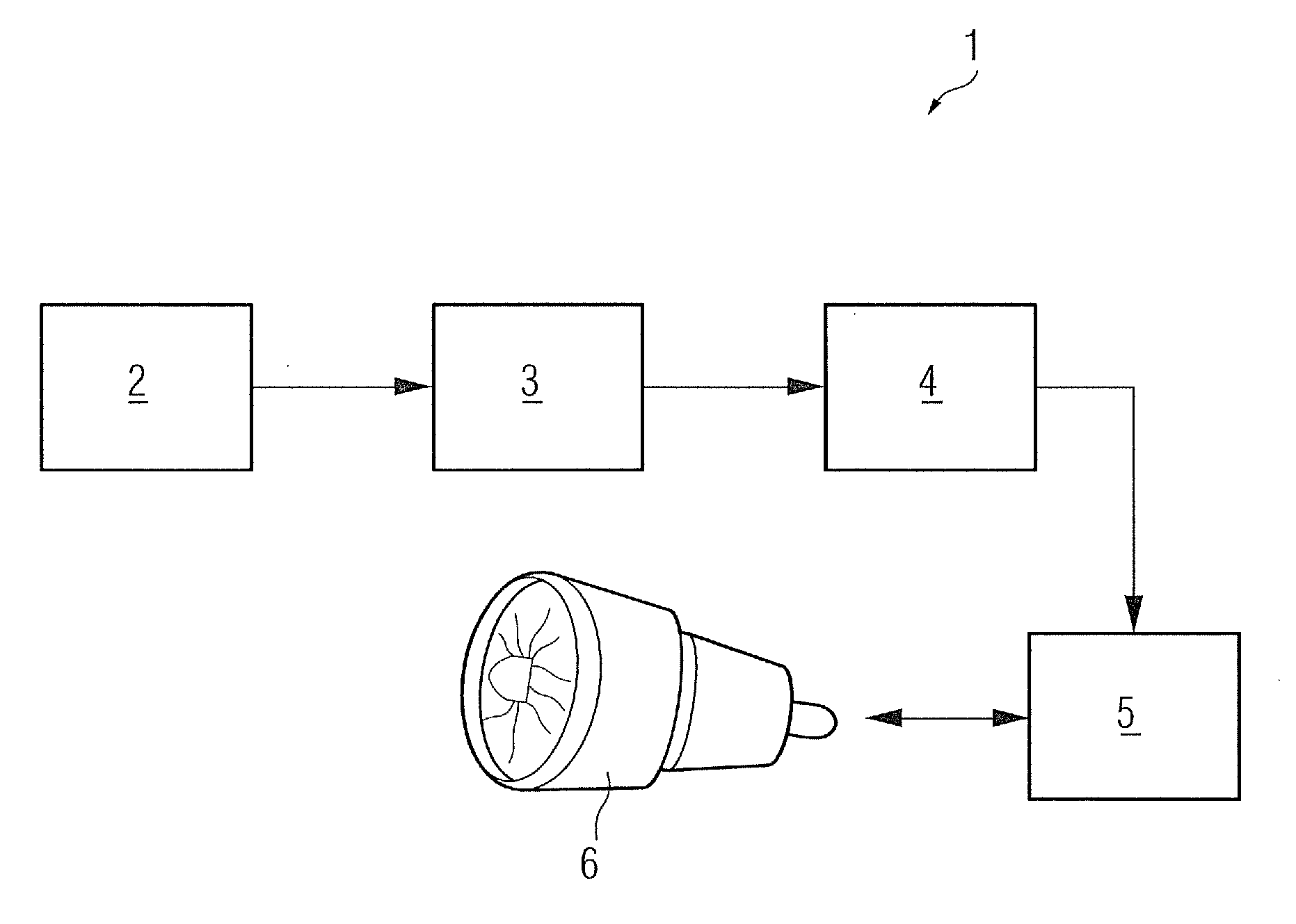
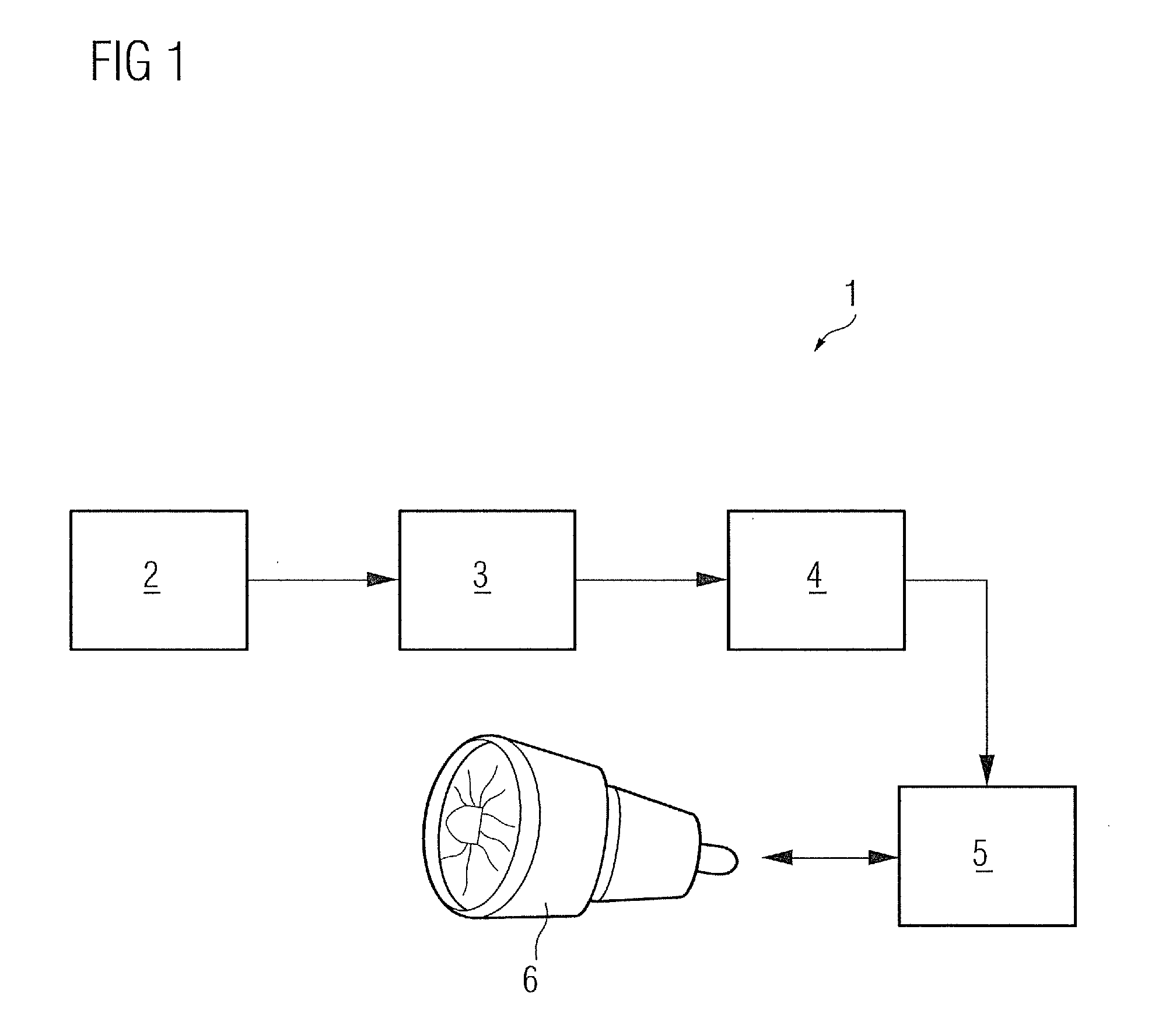
[0021]Referring no to FIG. 1 is illustrated an exemplary system 1 for operating a component 6 based on fatigue life estimation of the component 6. An important aspect of the fatigue process is plastic deformation. Fatigue cracks usually nucleate from plastic straining in localized regions. Therefore cyclic strain-controlled tests have been found to better characterize fatigue behavior of the component than cyclic stress-controlled tests, particularly in the low cycle fatigue (LCF) region. To that end, the illustrated system 1 broadly includes testing means 2 for obtaining strain-controlled LCF test data of the component 6 or a specimen representative of the component 6, modeling means 3 for fitting LCF material curves on the data samples obtained from the testing means 2, design means 4 for determining an estimated fatigue life of the component 6 on the basis of these LCF material curves, and control means 5 for controlling downtime or maintenance interval of the component 6 taking ...


PUM


Abstract

A method to estimate the fatigue life of a component operable under cyclic stress is provided. A system including testing means for performing a strain controlled test of a component or a representative specimen of the component, to obtain therefrom a first set of data samples including measured stress amplitude values for varying applied strain levels, and a second set of data samples including measured number of cycles to crack initiation for varying applied strain levels is also provided. The system further includes a modeling means for fitting a first low cycle fatigue material curve on the first set of data samples and a second low cycle fatigue material curve on the second set of data samples.

Description

FIELD OF INVENTION[0001]The present invention relates to a system and method for estimating fatigue life of components operating under cyclic stress, particularly, components subject to low-cycle fatigue (LCF).BACKGROUND OF INVENTION[0002]In a plurality of applications in technical systems parts or components can be subject to stresses which alternate or vary over time, of a mechanical or thermal nature for example. In such cases individual parts can for example be subject to direct mechanical stresses through the occurrence of compressive or tensile forces. A time-varying thermal stress of this type arises on the other hand for example for the parts or components in a turbine system, especially in a gas turbine, when the gas turbine is started up or shut down.[0003]Extreme cyclic loading, both mechanical and thermal, results in material fatigue, also referred to as low cycle fatigue (LCF), which, in many cases limits the life of the component. The design of the components with resp...

Claims


Application Information

Patent Timeline
IPC IPC(8): G01L1/00
CPCG01N3/32G01N2203/0007G01N2203/0016G01N2203/0218G01N2203/0073G01N2203/0208G01N2203/0064
Inventor ROLLMANN, GEORGBRUNELLI, MARCO CLAUDIO PIO
Owner SIEMENS ENERGY GLOBAL GMBH & CO KG
Why Eureka
Try Eureka