Eureka AIR delivers breakthrough ideas for toughest innovation challenges, trusted by R&D personnel around the world.

Method for improving creep resistance and low cycle fatigue properties of pressure-containing components

a technology of pressure-containing components and creep resistance, which is applied in the field of ductile iron alloys, can solve the problems of low cycle fatigue and creep, and achieve the effects of low cycle fatigue, significant increase of high temperature properties of ductile iron alloy, and reduced creep and fatigu

Active Publication Date: 2010-11-16
GE INFRASTRUCTURE TECH INT LLC
View PDF2 Cites 0 Cited by
  • Summary
  • Abstract
  • Description
  • Claims
  • Application Information

AI Technical Summary

Benefits of technology

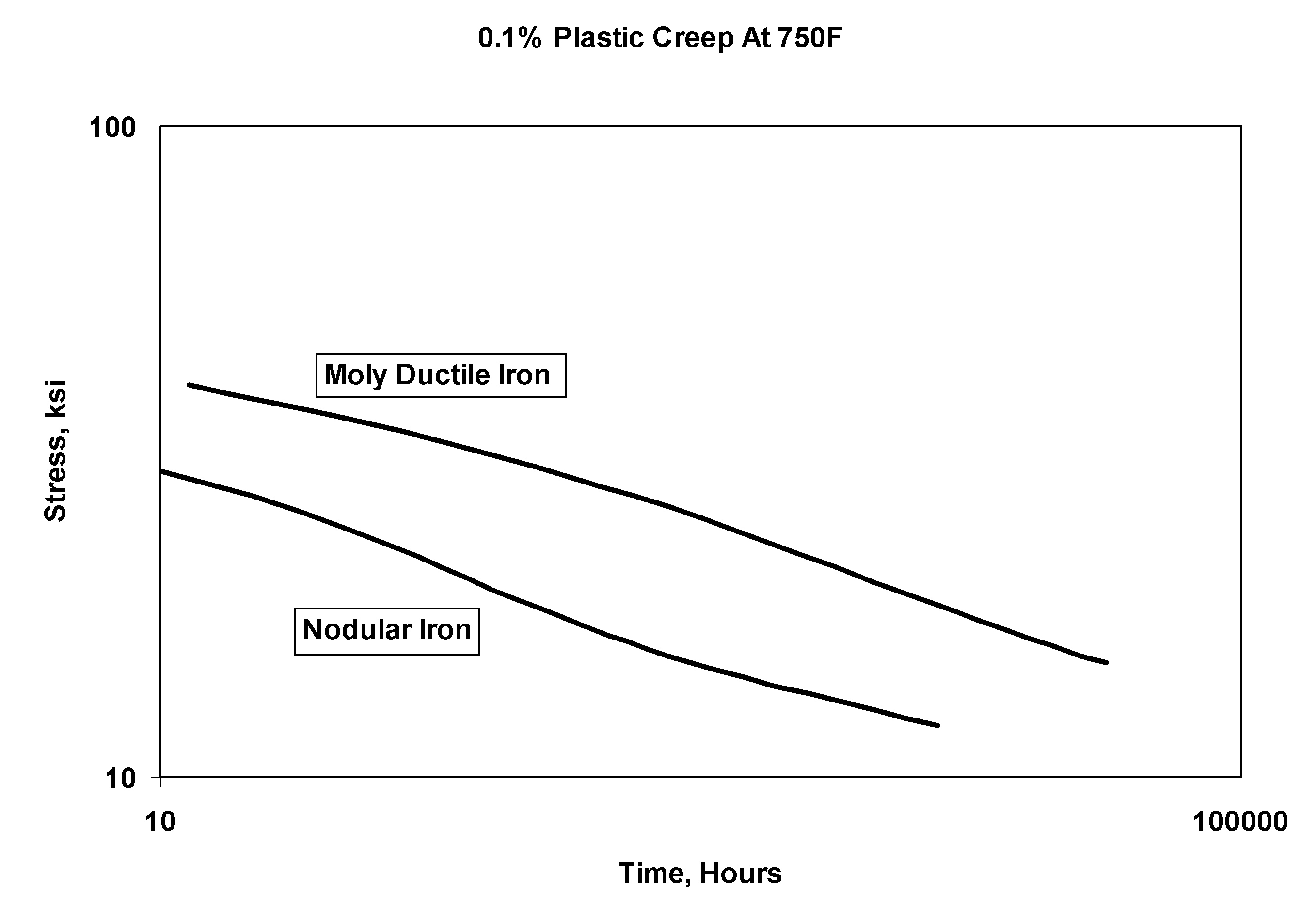
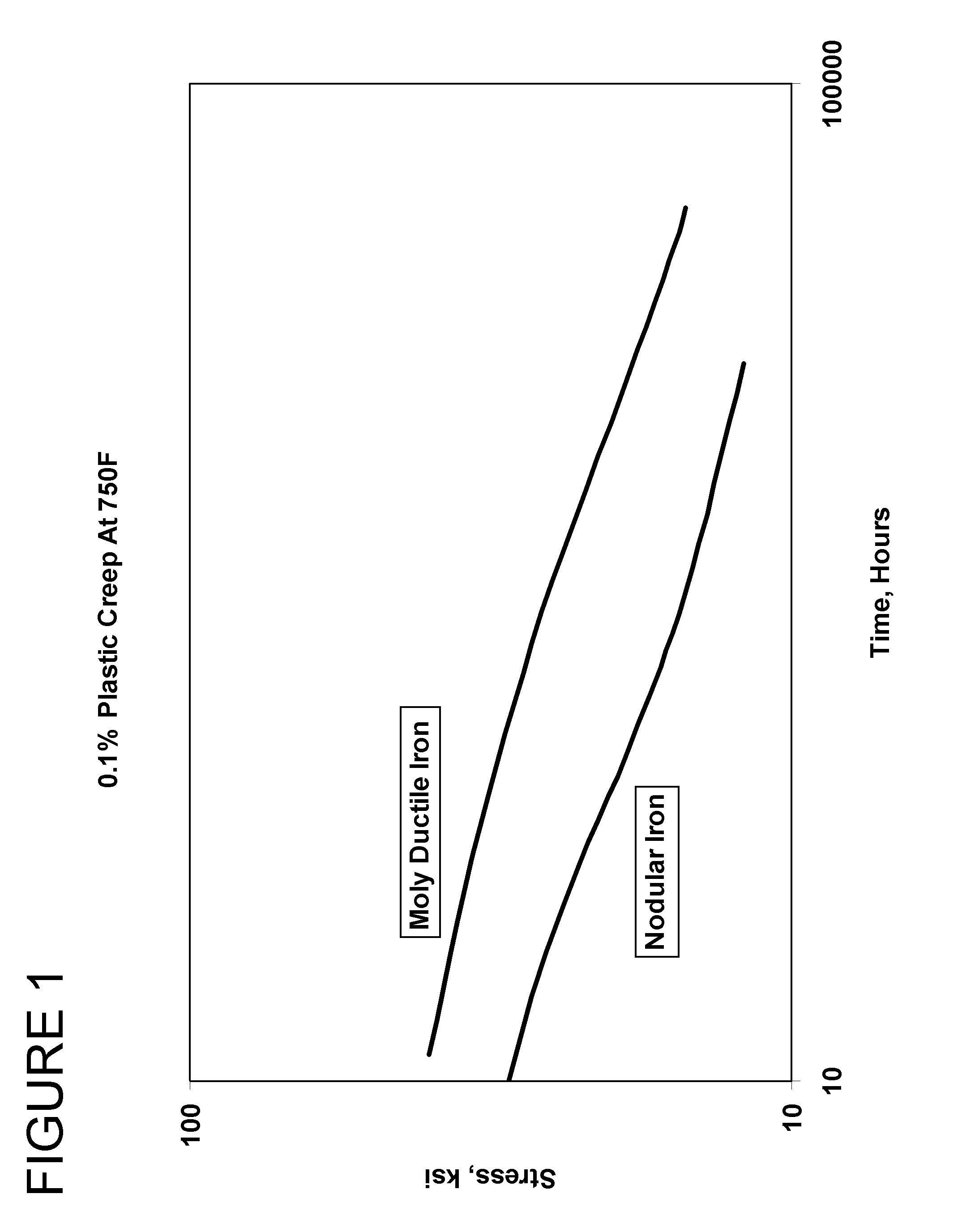
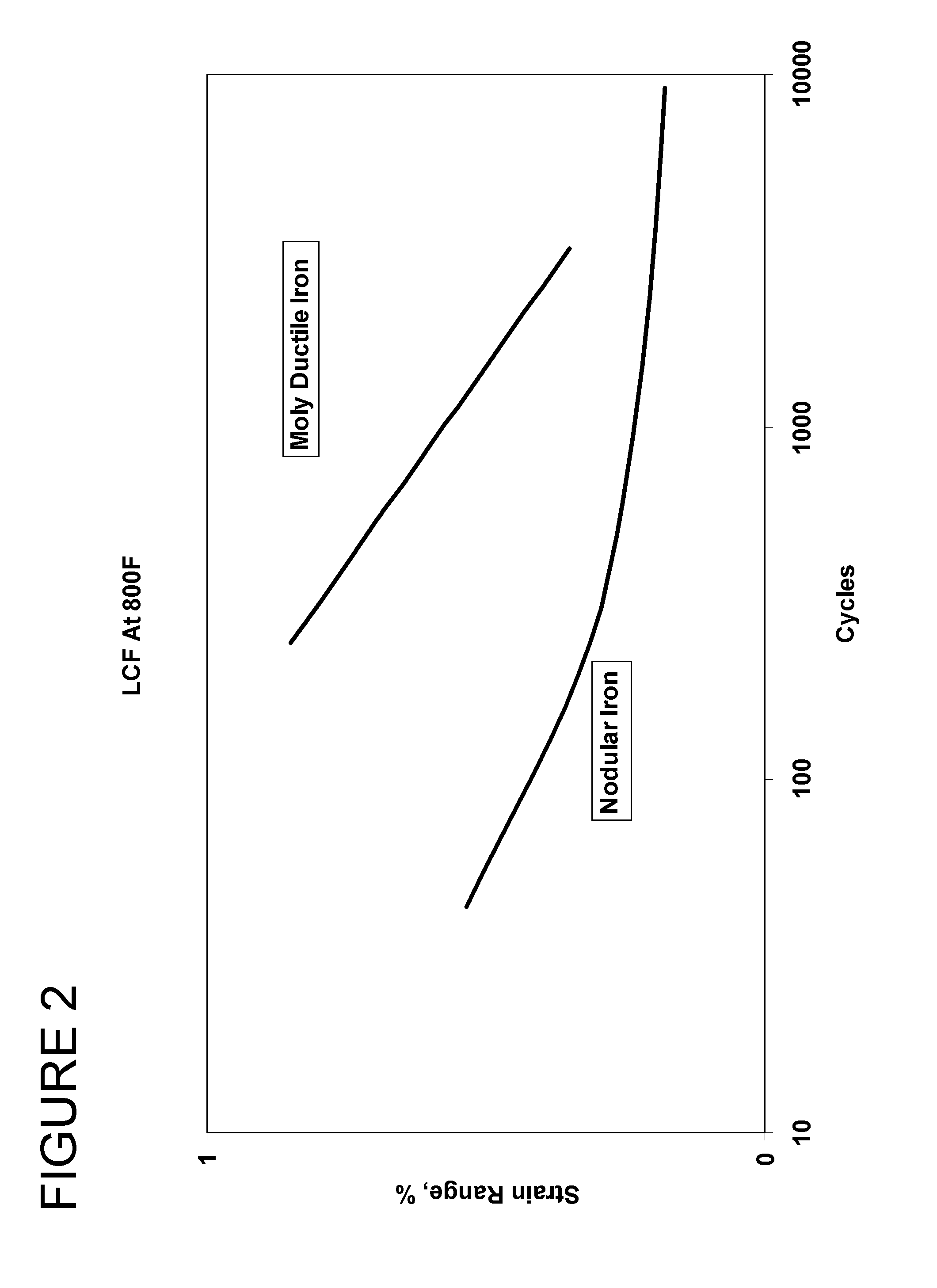
[0006]The present invention provides a method by which high temperature properties of a ductile iron alloy, including creep, rupture, tensile, and LCF properties, can be significantly increased over the conventional ASTM A395 / A395M-99 alloy. The method is particularly suitable for pressure-containing components that are located between the compressor and turbine sections of gas turbines, and therefore are subject to creep and low cycle fatigue. The method comprises modifying the ductile iron alloy to additionally contain 0.4 to 0.8 weight percent molybdenum and permit an increased silicon content of up to 2.75 weight percent, wherein the balance of the modified ductile iron alloy is iron and incidental impurities of, by weight, up to 0.3% manganese, up to 0.1% chromium, up to about 0.05% magnesium, up to 0.08% phosphorus, and up to 0.01% sulfur. A casting of the modified ductile iron alloy is produced and then annealed at a temperature of at least 725° C. for not less than five hours to eliminate carbides and / or stabilize pearlite in the casting. The annealed casting of the modified ductile iron alloy exhibits improved creep resistance and low cycle fatigue properties in comparison to an identical casting of the conventional ductile iron alloy.

Problems solved by technology

The method is particularly suitable for pressure-containing components that are located between the compressor and turbine sections of gas turbines, and therefore are subject to creep and low cycle fatigue.

Method used


Image

  • Method for improving creep resistance and low cycle fatigue properties of pressure-containing components
  • Method for improving creep resistance and low cycle fatigue properties of pressure-containing components
  • Method for improving creep resistance and low cycle fatigue properties of pressure-containing components

Examples


Embodiment Construction

[0010]The present invention provides a ductile iron alloy that exhibits excellent high temperature properties of the type required by compressor cases of industrial gas turbines. The alloy of this invention preferably contains the following elements in the following approximate proportions based on weight percent: 3.0% minimum carbon, 2.75% maximum silicon, 0.40% to 0.80% molybdenum, 0.3% maximum manganese, 0.1% maximum chromium, 0.08% maximum phosphorus, 0.01% maximum sulfur, and the balance iron and incidental impurities.

[0011]The levels of carbon, silicon and molybdenum are primarily responsible for obtaining the desired high temperature properties of the alloy. The role of silicon is generally to promote the strength, hardness, hardenability, and corrosion resistance of the base iron. Silicon levels above 2.75 weight percent are undesirable for use as a cast compressor case from the standpoint of reduced room temperature ductility, reduced castability, and reduced machinability....


PUM

PropertyMeasurementUnit
temperatureaaaaaaaaaa
operating temperatureaaaaaaaaaa
temperatureaaaaaaaaaa

Abstract

A method by which high temperature properties of a ductile iron alloy, including creep and LCF properties, can be increased for pressure-containing components that are subject to creep and low cycle fatigue. The method comprises modifying the ductile iron alloy to contain 0.4 to 0.8 weight percent molybdenum. A casting of the modified ductile iron alloy is produced and then annealed at a temperature of at least 725° C. for not less than five hours to eliminate carbides and / or stabilize pearlite in the casting. The annealed casting of the modified ductile iron alloy exhibits improved creep resistance and low cycle fatigue properties in comparison to an identical casting of a ductile iron alloy that does not contain molybdenum.

Description

CROSS REFERENCE TO RELATED APPLICATIONS[0001]This is a division patent application of U.S. patent application Ser. No. 10 / 905,145, filed Dec. 17, 2004 now abandoned.BACKGROUND OF THE INVENTION[0002]The present invention generally relates to ductile iron alloys. More particularly, this invention relates to modifying a ductile iron alloy to exhibit desirable properties for turbine compressor case components that must operate at temperatures exceeding the capability of conventional ductile iron alloys.[0003]Various alloys have been considered and used for compressor discharge cases and compressor case and other high-temperature components of industrial gas turbines. Compressor discharge cases are generally located immediately downstream from the compressor of a gas turbine, while compressor cases are still farther downstream and connect compressor discharge cases with the first stage of the turbine section. Because of the high pressures and elevated temperatures sustained between the c...

Claims


Application Information

Patent Timeline
Patent Type & Authority Patents(United States)
IPC IPC(8): C21D5/00C22C37/10
CPCC21D1/26C21D5/00C22C37/10C21D5/02C21D5/06C21D2211/009
Inventor BROWN, MARK ROGERTIPTON, THOMAS ROBBINSXU, LIMING
Owner GE INFRASTRUCTURE TECH INT LLC
Why Eureka
Eureka Blog
Learn More