Eureka AIR delivers breakthrough ideas for toughest innovation challenges, trusted by R&D personnel around the world.

Glass structure, glass structure forming system, and method of making glass structure

Pending Publication Date: 2020-06-11
CORNING INC
View PDF4 Cites 1 Cited by
  • Summary
  • Abstract
  • Description
  • Claims
  • Application Information

AI Technical Summary

Benefits of technology

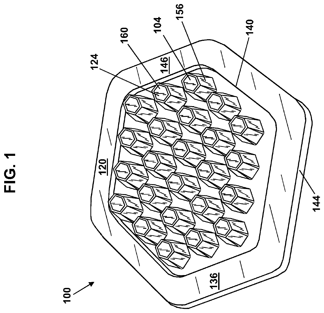
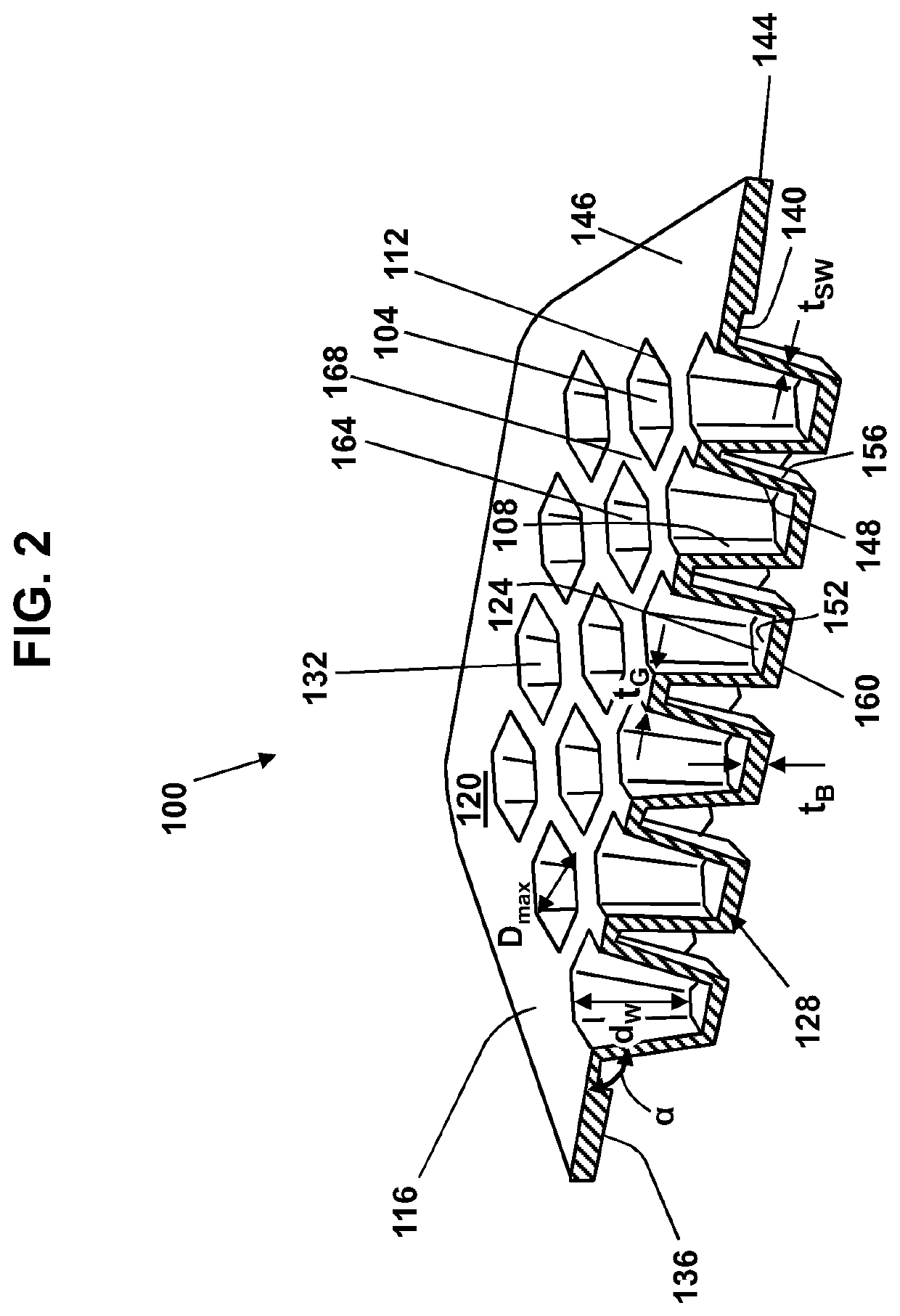
The present patent provides a multi-well glass-containing structure, a system to form it, and a method of manufacturing it. The structure has at least one well with a specific aspect ratio and inner surface roughness. The system includes a mold, a furnace, and a pressing element to form the glass-containing sheet into the wells. The method involves heating the mold and sheet, applying pressure to conform the sheet to the mold, cooling the sheet, and removing it from the mold. The technical effects include a more precise and uniform well structure with improved depth and smooth inner surface, as well as a simplified manufacturing process.

Problems solved by technology

For example, hot gob pressing may have a low glass cost relative to the other processes, but result in surface roughness and limited dimensional precision; reactive ion etching may have high dimensional precision, but generally a high cost relative to the other processes; chemical etching may have a lower cost than reactive ion etching, but at still a high cost, and may result in irregular surfaces and roughness; photosensitive glass etching may also be a high cost process, but can result in high dimensional precision and thin features; high viscosity repressing can result in high dimensional precision and medium cost.

Method used


Image

  • Glass structure, glass structure forming system, and method of making glass structure
  • Glass structure, glass structure forming system, and method of making glass structure
  • Glass structure, glass structure forming system, and method of making glass structure

Examples


Embodiment Construction

[0026]The disclosure is described more fully hereinafter with reference to the accompanying drawings, in which embodiments of the disclosure are shown. This disclosure may, however, be embodied in many different forms and should not be construed as limited to the embodiments set forth herein. Rather, these embodiments are provided so that this disclosure is thorough, and will fully convey the scope of the disclosure to those skilled in the art. In the drawings, the size and relative sizes of layers and regions may be exaggerated for clarity. Like reference numerals in the drawings denote like elements.

[0027]It will be understood that when an element or layer is referred to as being “on” or “connected to” another element or layer, it can be directly on or directly connected to the other element or layer, or intervening elements or layers may be present. In contrast, when an element or layer is referred to as being “directly on” or “directly connected to” another element or layer, the...


PUM

PropertyMeasurementUnit
Fractionaaaaaaaaaa
Fractionaaaaaaaaaa
Fractionaaaaaaaaaa

Abstract

A multi-well glass-containing structure, and system and method to manufacture the structure are provided. The structure can be a glass plate having a well defined by a rim at a top of the plate to define a well opening, a well bottom at a bottom of the plate spaced away from the rim by a well wall extending from the rim to the well bottom. A well aspect ratio of the depth of the well to a maximum surface dimension of the well opening can be in a range from 40% to 100%. The inner surface of the well can have an average roughness, Ra, of less than 600 nm. The system can include a mold with a coefficient of thermal expansion that matches the glass-containing structure and the method can include forming the glass plate at a viscosity of about 105 to 107,6 poises.

Description

CROSS-REFERENCE TO RELATED APPLICATIONS[0001]This application claims the benefit of priority of U.S. Provisional Application Ser. No. 62 / 491,582 filed on Apr. 28, 2017 the contents of which are relied upon and incorporated herein by reference in their entirety as if fully set forth below.BACKGROUNDField[0002]Exemplary embodiments of the present disclosure relate to a glass structure, a glass structure forming system, and a method of making a glass structure. More particularly, exemplary embodiments of the present disclosure relate to glass multi-well structures having high well depth to well opening ratio and low average surface roughness, glass multi-well structure forming systems comprising molds of predetermined coefficient of thermal expansion and methods of manufacturing glass multi-well structures having high well depth to well opening ratio and low average surface roughness.Discussion of the Background[0003]There can be numerous applications for glass elements comprising well...

Claims


Application Information

Patent Timeline
IPC IPC(8): C03B23/035B01L3/00
CPCC03B23/0357B01L2300/12C03C2204/08B01L2300/0829B01L3/5085C03B17/02C03B17/064C03B23/02C03B23/03C03B23/0302B01L2200/12B32B3/28B32B17/06
Inventor BOEK, HEATHER DEBRADANNOUX, THIERRY LUC ALAIN
Owner CORNING INC
Why Eureka
Eureka Blog
Learn More