Glass structure and method for producing the same

a technology of glass structure and glass, applied in the direction of glass tempering apparatus, manufacturing tools, instruments, etc., can solve the problems of large etching apparatus, wet etching, and difficulty in reducing the machining threshold, so as to reduce the machining threshold, improve the shape controllability, and improve the effect of processability

Inactive Publication Date: 2007-05-15
NIPPON SHEET GLASS CO LTD
View PDF6 Cites 32 Cited by
  • Summary
  • Abstract
  • Description
  • Claims
  • Application Information

AI Technical Summary

Benefits of technology

[0025]According to the invention, laser machining-purpose glass containing uniformly an element which can be imported into glass without ion exchange when the glass is melted and which absorbs laser beam energy to reduce a machining threshold is used as a workpiece, so that good processability can be obtained even in the inside of the glass. As a result, shape controllability can be improved even in the inside of the glass, so that a machined glass article high in the degree of freedom three-dimensionally can be obtained.
[0026]In the producing method according to the invention, a glass structure having a predetermined three-dimensional shape can be produced easily with good controllability if energy of the applied laser beam is controlled three-dimensionally.
[0027]To obtain a complex machined glass article high in the degree of freedom three-dimensionally, an optical system through which the laser beam passes till the laser beam is applied on a specimen after emission of the laser beam needs to become so complex that energy of the laser beam is attenuated greatly. If machining is performed not by a high-output laser but by a more general-purpose laser light source, it is preferable that the machining threshold is as low as possible. In the existing circumstances an effect of widening the limit of lasers allowed to be used can be obtained when the threshold is not larger than 1.0 J / cm2 per laser beam pulse as described above.
[0028]In the invention, the laser machining-purpose glass contains at least one member selected from the group consisting of titanium, iron, vanadium, bismuth, lead, thallium, tin, cerium, rhodium, and cobalt. This is effective in reducing the laser machining threshold of the glass because these elements exhibit high absorption in the wavelength range of the laser beam used in the invention.

Problems solved by technology

Wet etching, however, has a problem in management and disposal of the etching liquid.
Dry etching has a problem that an etching apparatus, itself large in scale, is required because equipment such as a vacuum vessel, etc. is required.
Moreover, there is also a problem that these etching methods are not efficient because a pattern mask or the like must be formed by a complex photolithographic technique.
Glass is however apt to crack when machined because it is a brittle material.
For this reason, it was not easy to use laser machining for the purpose of fine treatment.
In glass containing a large amount of alkaline metal, however, a phenomenon that diffusion of silver ions into the glass is disturbed because of reduction of silver ions in a limited region near surface of the glass occurs though silver ions can be imported into the glass by ion exchange.
Hence, there is a problem in production efficiency.

Method used


Image

  • Glass structure and method for producing the same
  • Glass structure and method for producing the same
  • Glass structure and method for producing the same

Examples


embodiment 1

(Embodiment 1)

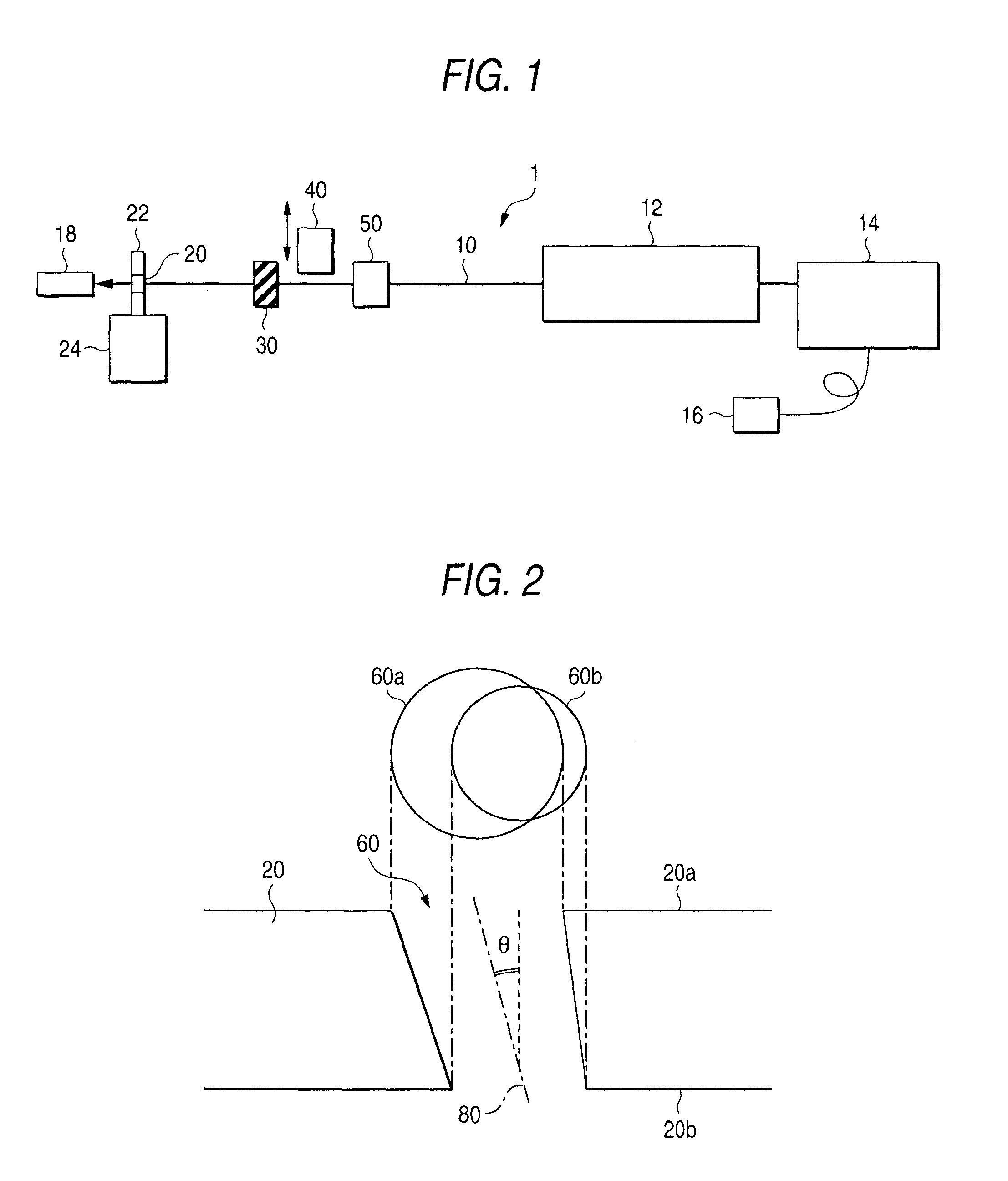
[0047]The substrate holder 22 was inclined by a predetermined angle θ from a direction perpendicular to the optical axis of the laser beam 10 to thereby produce an oblique hole inclined at the angle to the thickness direction of the glass substrate 20. The angle of the oblique hole can be adjusted by adjustment of the inclination angle θ of the specimen.

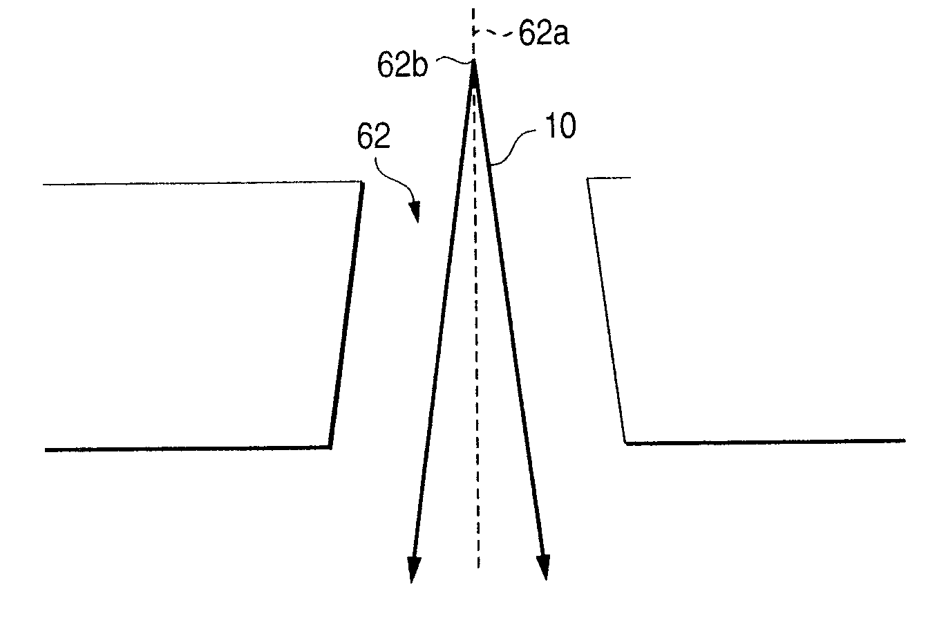
[0048]FIG. 2 typically shows sectional and plan views of a through-hole 60 formed in a 0.3 mm-thick glass substrate 20 fixed to be inclined at an angle θ=15° to the optical axis of the laser beam 10 when irradiation energy per unit area of the laser beam is constant (8 J / cm2). (For convenience' sake, the hole diameter shown in FIG. 2 is magnified to be larger than the actual value compared with the thickness of the substrate.)

[0049]Incidentally, the beam diameter of the laser beam 10 on a front surface of the substrate was set at about 100 μm. The shapes 60a and 60b of the hole 60 at front and rear surfaces 20a and 20b ...

embodiment 2

(Embodiment 2)

[0053]The third and fourth harmonics of an Nd:YAG laser was used as a laser beam. Machining was performed while the irradiation power of the laser beam was changed by the attenuator 50. During the machining, the stage 24 was fixed and the distance between the laser light source 12 and the glass substrate 20 was kept constant. The initial value of irradiation energy per unit area was set at 15 J / cm2. The irradiation energy was reduced with the passage of time, that is, the irradiation energy was changed continuously so that it became 5 J / cm2 when the hole pierced the glass substrate 20. As the irradiation power decreased, the beam diameter of the laser beam decreased.

[0054]Under the condition, there was obtained a through-hole having a taper angle of about 10° which was large compared with the case where the irradiation power was constant. If the laser beam irradiation was stopped before the machined portion pierced the substrate, it was possible to form a cavity having...

embodiment 3

(Embodiment 3)

[0057]The third and fourth harmonics of an Nd:YAG laser were used as the laser beam. During machining, the stage 24 was moved in parallel to the direction of the optical axis of the laser beam 10 to change the distance L between the laser light source 12 and the glass substrate 20. While the diameter of the laser beam applied on the glass substrate 20 was changed in this manner, a through-hole or a cavity was produced. The irradiation power of the laser beam was kept constant during the machining.

[0058]Because a specimen is placed in front of a beam waist which is formed when the laser beam is converged by a lens, irradiation energy per unit area increases and the area irradiated with the laser beam decreases as the distance L between the light source and the surface irradiated with the laser beam increases.

[0059]The distance L between the laser light source 12 and the glass substrate 20 at the time of start of machining was set at 95 mm. The distance L was adjusted so...


PUM

PropertyMeasurementUnit
wavelengthaaaaaaaaaa

Abstract

A limited portion of a surface of a glass substrate is removed by application of a laser beam on the limited portion of the glass substrate to thereby produce a glass structure according to the invention. The glass substrate contains at least one element such as titanium, iron, vanadium, bismuth, lead, thallium, tin, cerium, rhodium or cobalt capable of absorbing energy of the laser beam and has a threshold of not larger than 1.0 J/cm2 per laser beam pulse in terms of machining energy of the laser beam. When such a glass substrate 21 is used, a glass structure having a through-hole 61 or cavity optional in sectional shape can be formed by irradiation with the laser beam 10.

Description

[0001]The present application is based on Japanese Patent Application No. P2002-45667, the entire contents of which are incorporated herein by reference.BACKGROUND OF THE INVENTION[0002]1. Field of the Invention[0003]The present invention relates to a glass structure having a through-hole or a cavity and particularly to a glass structure produced by laser beam irradiation and a method for producing the glass structure.[0004]2. Related Art[0005]A glass structure constituted by a finely treated glass substrate is used as an optical component used in optical communication or as a micro lens incorporated in a display device. As a method for finely treating such a glass substrate, wet etching using an etching liquid such as hydrofluoric acid or dry etching such as reactive ion etching is heretofore used generally.[0006]Wet etching, however, has a problem in management and disposal of the etching liquid. Dry etching has a problem that an etching apparatus, itself large in scale, is requir...

Claims


Application Information

Patent Timeline
Patent Type & Authority Patents(United States)
IPC IPC(8): C03C21/00G02B3/00B23K26/00B23K26/073C03B23/02C03B33/02C03B33/08C03C4/08C03C14/00C03C23/00
CPCB23K26/073B23K26/383C03B33/082C03C23/0025B23K26/385Y10T428/24273B23K26/384B23K26/389
Inventor KOYO, HIROTAKATSUNETOMO, KEIJI
Owner NIPPON SHEET GLASS CO LTD
Why Eureka
Try Eureka