
System and method with optimized polymer and metal structural components for electronic assembly

a technology of electronic assembly and polymer, applied in the direction of electrical apparatus casings/cabinets/drawers, instruments, configuration cad, etc., can solve the problems of reducing the use of metal, and generally not meeting the required mechanical and electrical properties, so as to achieve the effect of maximizing the weight saving opportunity

Active Publication Date: 2020-06-11
HONEYWELL INT INC
View PDF0 Cites 14 Cited by
  • Summary
  • Abstract
  • Description
  • Claims
  • Application Information

AI Technical Summary

Benefits of technology

This patent describes a method and system for constructing an electronic assembly using a structural component that combines a metal element and a polymer element. By analyzing the requirements for both electrical and mechanical properties, the minimum material thickness and area of the metal element for achieving electromagnetic shielding and electrical bonding, and the maximum polymer element proportion to meet the structural and thermal requirements, the structural component is designed to meet all requirements while minimizing the use of metal. This design results in a lightweight and well-balanced structural component that can be used in electronic assemblies.

Problems solved by technology

The use of metal has the drawback of weight.
Conventionally in an electronic system packaging, if a material other than metal is considered for a component, a number of limitations inhibit its use.
Though there are many available non-metal materials that weigh less than metal, they generally do not meet the required mechanical and electrical properties.
Since most of the parts in an electronic packaging system require certain characteristics that are provided by metal, limited opportunities have existed for the use on non-metal materials.

Method used


Image

  • System and method with optimized polymer and metal structural components for electronic assembly
  • System and method with optimized polymer and metal structural components for electronic assembly
  • System and method with optimized polymer and metal structural components for electronic assembly

Examples


Embodiment Construction

[0024]The following detailed description is merely exemplary in nature and is not intended to limit the invention or the applications and uses of the invention. Furthermore, there is no intention to be bound by any theory presented in the preceding background or the following detailed description.

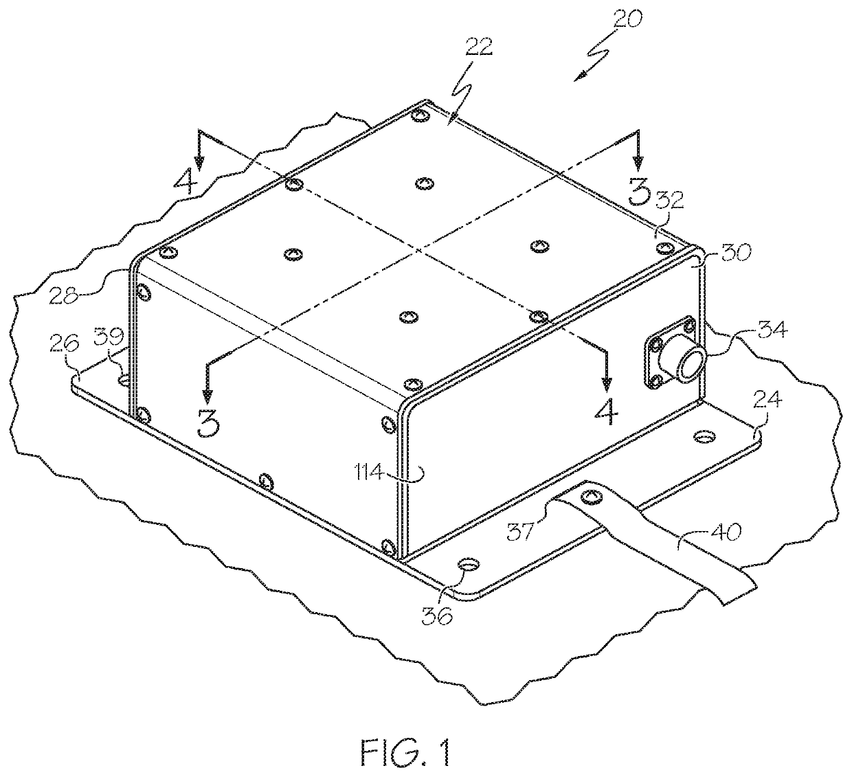
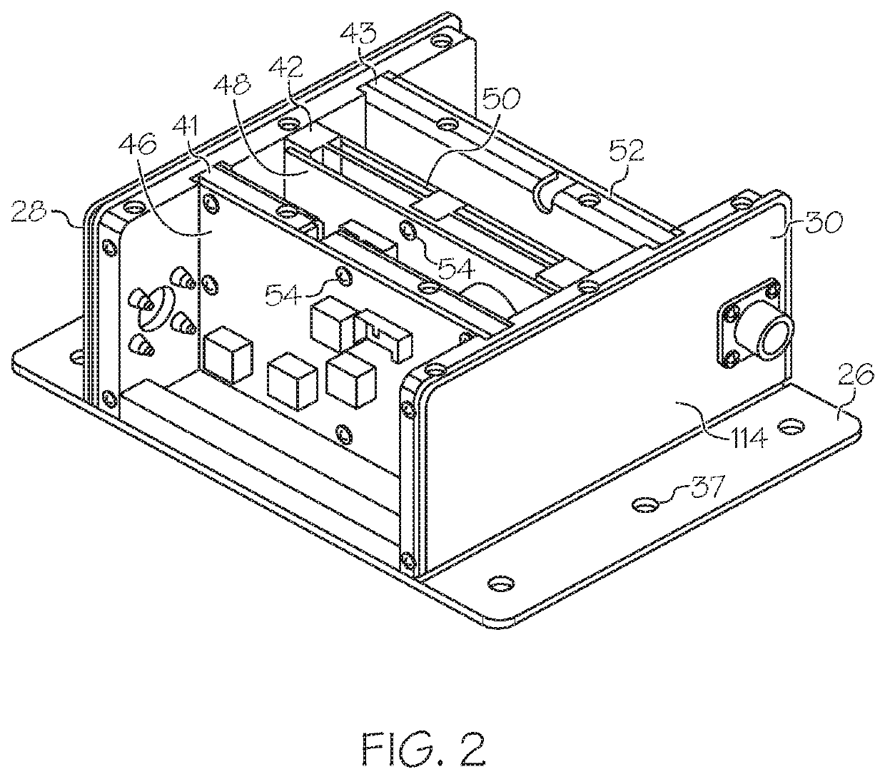
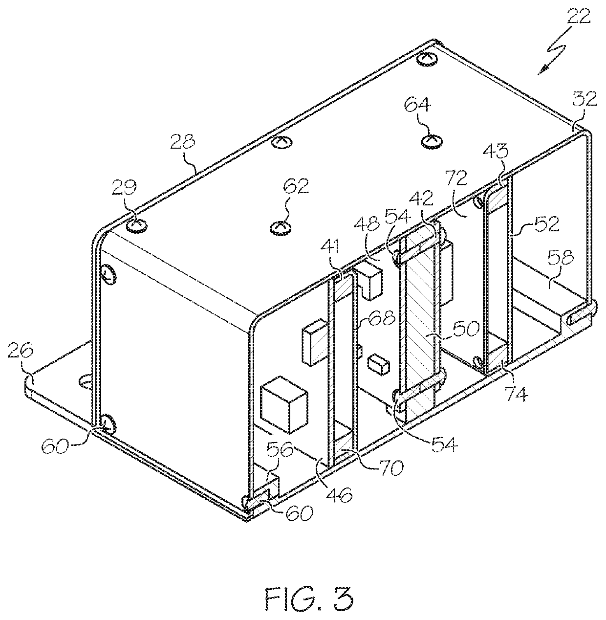
[0025]The description contained herein relates to electronic systems and the packaging thereof, and in certain examples is detailed in the context of a manufactured environment, for example, an aircraft. In manufactured environments, various types of systems are electronically controlled to supply different electric power ratings at a variety of voltage and current profiles. These systems may include various forms of electronic control assemblies in which components are assembled via an electronic packaging system. The components include those that carry out electrical / electronic functions, and those that provide structural an electrical properties to support the requirements of the assembl...


PUM


Abstract

A system and method of constructing an electronic assembly. A structural component is identified as a candidate for forming as a combined construction of a metal element and a polymer element. A minimum material thickness required of the metal element for achieving a required electromagnetic shielding property is determined. A minimum area required of the metal element for achieving a required electrical bonding property is determined. A maximum polymer element proportion of the structural component that meets a required structural property and a required thermal property is determined. The structural component is designed with the metal element having the minimum material thickness and the minimum area and with the polymer element having the maximum polymer element proportion. The structural component is manufactured from the polymer element and the metal element to meet the mechanical and electrical properties, and the structural component in the electronic assembly.

Description

TECHNICAL FIELD[0001]Embodiments of the subject matter described herein relate generally to light weight electronic assemblies. More particularly, embodiments of the subject matter relate to systems and methods optimizing the use of a light weight polymers in combination with metal for structural components of an electronic assembly.BACKGROUND[0002]Typically, conventional electrical and electronic assembly systems used in a wide range of applications are secured from the environment effects using enclosures made of metals. For example, electronic assemblies in high power applications and those used under harsh environment conditions use metals for structural elements. Metal components are used due to their desirable mechanical properties, availability, manufacturability, and electrical properties. Accordingly, there is a bias toward the use of metal to make various components.[0003]In the field of vehicle applications such as aircraft, different metals and combinations of metals are...

Claims


Application Information

Patent Timeline
IPC IPC(8): H05K9/00H05K5/00H05K5/03H05K7/20G06F17/50
CPCG06F2111/20H05K5/006G06F30/23H05K5/0056H05K7/20436G06F30/39H05K9/0049H05K5/03H05K7/1461H05K9/0062
Inventor MURUGESAN, GOKULKUSTAGI, SANTOSHDESAI, RAGHUVEER HANUMANTHRAOVALIVETI, V
Owner HONEYWELL INT INC
Learn More