
System and methods for attaining optimal precision stereoscopic direction and ranging through air and across refractive boundaries using minimum variance sub-pixel registration

Active Publication Date: 2020-06-18
FLEMING MWANYOHA SADIKI PILI
View PDF0 Cites 2 Cited by
  • Summary
  • Abstract
  • Description
  • Claims
  • Application Information

AI Technical Summary

Benefits of technology

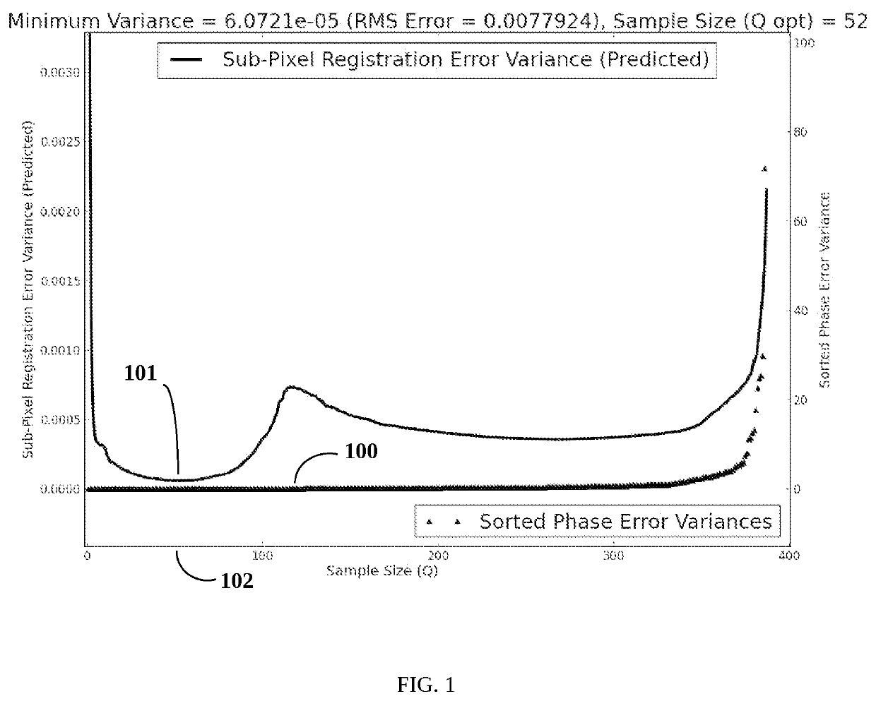
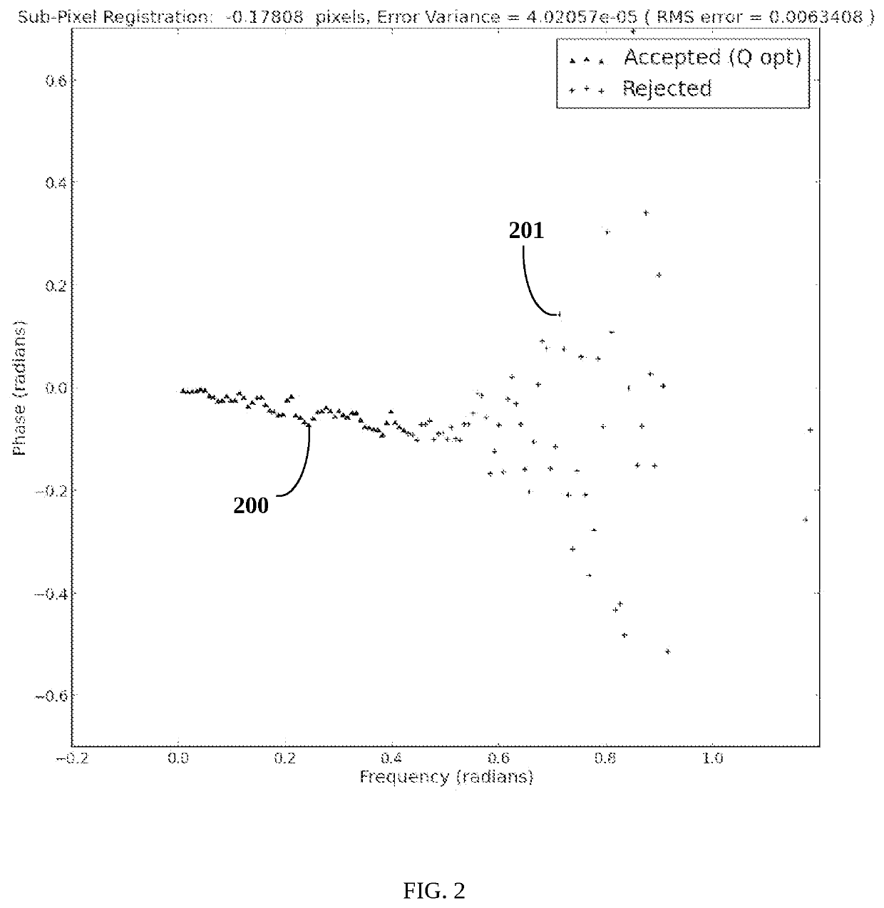
The present invention improves the accuracy of registering pixels by using a special method to estimate the angle at which objects appear to be located. This method selected the best frequencies to use, to minimize the impact of phase noise, and tracked changes in measurement and estimation as they happen in the system. This helps to provide real-time error analysis for the user, showing the precision of each estimate on the same screen as the subject under focus.

Problems solved by technology

Thus, such techniques do not produce a consistent estimate based on an arithmetic mean of multiple measurements, wherein the estimate's error variance could decay as the number of measurements is increased, thus producing unbiased, high-precision estimates.
Accordingly, such prior art interpolation techniques produce estimates that are often unpredictably biased relative to the true non-integer pixel offset and lack precision.
Another shortcoming of the prior art is lack of an optimal strategy for phase noise suppression.
Phase noise limits the precision achievable with phase correlation approaches.
Such approaches are heuristic and tend to distort the cross-power spectrum phase response in a non-predictable manner, which contributes to the bias in their associated sub-pixel registration estimates.
A final shortcoming of prior art approaches is the lack of quantifying and reporting the estimation error variance.

Method used


Image

  • System and methods for attaining optimal precision stereoscopic direction and ranging through air and across refractive boundaries using minimum variance sub-pixel registration
  • System and methods for attaining optimal precision stereoscopic direction and ranging through air and across refractive boundaries using minimum variance sub-pixel registration
  • System and methods for attaining optimal precision stereoscopic direction and ranging through air and across refractive boundaries using minimum variance sub-pixel registration

Examples


Embodiment Construction

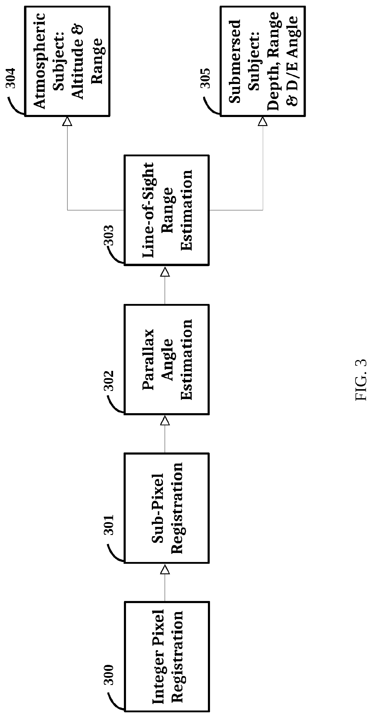
[0048]The system of the present invention comprises six methods as indicated in the overview shown in FIG. 3.

[0049]The purpose of the first method shown in Overview FIG. 3, Integer Pixel Registration 300, is to determine the integer horizontal pixel offset of a subject captured in a left stereo image relative to a right stereo image. Integer Pixel Registration 300 informs method Sub-Pixel Registration 301 how to align subject pixels shared in common between left and right, and discard pixels that do not appear in both subjects, thereby reducing the effective noise level presented to Sub-Pixel Registration 301. Method Integer Pixel Registration 300 comprises ten steps as illustrated in FIG. 4A.

[0050]The first step of method Integer Pixel Registration 300 is Stereo Image Capture 400, which simultaneously captures left and right images using a stereo-camera having corresponding left and right optical sensors separated at a known distance, and operating in the visible or infrared spectr...


PUM


Abstract

A system and methods for attaining optimal precision digital image stereoscopic direction and ranging through air and across a refractive boundary separating air from a liquid or plasma using stereo-cameras, and employing a minimum variance sub-pixel registration method for determining precise estimates of the parallax angle between left and right stereo images. The system and methods can also track measurement and estimation variances as they propagate through the system in order to provide a comprehensive precision analysis of all estimated quantities.

Description

BACKGROUND OF THE INVENTION[0001]The present invention relates to the precise estimation of direction and range to remote objects submersed in a liquid, such as water, or a plasma, as well as remote, atmospheric objects residing in air, by means of a stereoscopic camera system.[0002]Miniaturization of stereo-camera systems, for example in the field of smart-phones and robotics, has created a trend of progressively smaller camera separation distances requiring the ability to resolve ever minute parallax angles. Moreover, the ability to accurately estimate far-field object distances from digital images is sure to have a wide reaching impact on both real-time and offline applications for law enforcement and criminal forensics, security and surveillance, surveying, aerial drones and machine vision in general, but it requires accurate estimates of slim parallax angles. And notwithstanding the availability of high-resolution cameras, in order to accurately measure ever smaller parallax an...

Claims


Application Information

Patent Timeline
IPC IPC(8): G06T3/00G06T3/40G06T7/00G06T7/37G06T7/38H04N13/225
CPCG06T7/97G06T3/0068H04N2013/0074G06T7/38G06T3/4084G06T2207/10012H04N13/225G06T7/37H04N13/239G06T7/593G06T2207/10024G06T2207/20056G06T3/14
Inventor FLEMING-MWANYOHA, SADIKI PILI
Owner FLEMING MWANYOHA SADIKI PILI
Learn More