Lubricating oil distributor for a mechanical reduction gear of an aircraft turbine engine

Pending Publication Date: 2020-06-25
SAFRAN TRANSMISSION SYST
View PDF6 Cites 1 Cited by
  • Summary
  • Abstract
  • Description
  • Claims
  • Application Information

AI Technical Summary

Benefits of technology

[0013]This type of oil distributor therefore comprises two independent circuits. The first circuit can be used to supply oil to the gearing teeth in the reduction gear, such as the gearings of the sun gear and of the planet gears of the reduction gear. The lubricating oil of the first circuit is generally at a temperature T1. The second circuit can be used to supply oil to the bearings of the planet gears of the reduction gear. The lubricating oil of the second circuit is generally at a temperature T2 that is greater than T1. The distributor therefore supplies the reduction gear with two oils at different temperatures, these temperatures being selected to optimise the lubricating of the parts of the reduction gear. During operations, the oil that has lubricated these parts is projected radially outwards by centrifugal forces and has a temperature greater than its initial tem

Problems solved by technology

This cold oil is thus likely to be heated by the oil that served to lubricate the reduc

Method used


Image

  • Lubricating oil distributor for a mechanical reduction gear of an aircraft turbine engine
  • Lubricating oil distributor for a mechanical reduction gear of an aircraft turbine engine
  • Lubricating oil distributor for a mechanical reduction gear of an aircraft turbine engine

Examples


Embodiment Construction

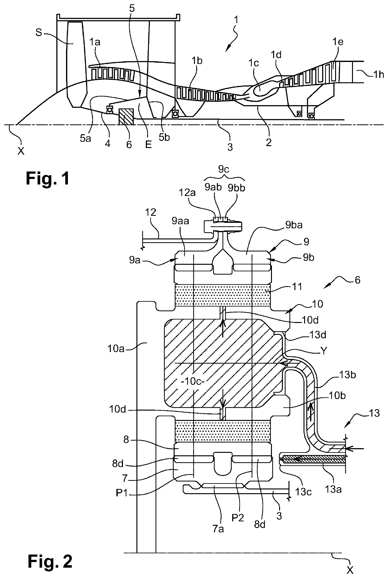
[0038]FIG. 1 describes a turbine engine 1 that comprises, conventionally, a fan S, a low-pressure compressor 1a, a high-pressure compressor 1b, an annular combustion chamber 1c, a high-pressure turbine 1d, a low-pressure turbine 1e, and an exhaust pipe 1h. The high-pressure compressor 1b and the high-pressure turbine 1d are connected by a high-pressure shaft 2 and form with the latter a high-pressure (HP) body. The low-pressure compressor 1a and the low-pressure turbine 1e are connected by a low-pressure shaft 3 and form with the latter a low-pressure (LP) body.

[0039]The fan S is driven by a fan shaft 4, which is driven with the LP shaft 3 by means of a reduction gear 6. The reduction gear 6 is generally of the planetary or the epicyclic type.

[0040]Although the following description relates to a planetary reduction gear or an epicyclic reduction gear, it also applies to a mechanical differential in which the three components, i.e. the planet-carrier, the ring gear and the sun gear a...


PUM


Abstract

Lubricating oil distributor for a mechanical reduction gear of a turbine engine, in particular of an aircraft, wherein it has a general annular shape around an axis X and is formed of a single part, the distributor including first and second independent oil circuits, the first oil circuit including a first oil inlet connected by a first annular chamber to several oil outlets, and the second oil circuit including a second oil inlet connected by a second annular chamber to several oil outlets, the first chamber including a section that is at least partially nested in a section of the second chamber.

Description

TECHNICAL FIELD OF THE INVENTION[0001]The present invention relates to the field of reduction gears for turbine engines, in particular of an aircraft.TECHNICAL BACKGROUND[0002]The state of the art includes, in particular, documents WO-A1-2010 / 092263, FR-A1-2 987 416, FR-A1-3 041 054, US-A1-2013 / 283756 and FR-A1-3 047 279.[0003]The purpose of a mechanical reduction gear is to change the speed to torque ratio between the input shaft and the output shaft of a mechanical system.[0004]The new generations of bypass turbine engines, in particular turbine engines with high dilution rates, comprise a mechanical reduction gear that drives the shaft of a fan. Usually, the purpose of the reduction gear is to transform the “fast” rotational speed of a power turbine into a slower rotational speed for the shaft driving the fan.[0005]This type of reduction gear comprises a central pinion, termed sun gear, a ring gear and pinions termed planet gears, the latter engaging between the sun gear and the ...

Claims


Application Information

Patent Timeline
IPC IPC(8): F01D25/18B64D33/08F16H57/04
CPCB64D33/08F01D25/18F16H57/042F16H57/0486F16H57/0479F16H57/0482F16H57/0456F16H57/0413F02C7/06F02C7/36F16H57/0431F16H57/0426
Inventor CHARRIER, MATHIEU JEANGOUIN, GILLES GASTON JACQUESMORELLI, BORIS PIERRE MARCEL
Owner SAFRAN TRANSMISSION SYST
Why Eureka
Try Eureka