Spatial Redistributors and Methods of Redistributing Mm-Wave Signals

Active Publication Date: 2020-06-25
CALIFORNIA INST OF TECH
View PDF0 Cites 9 Cited by
  • Summary
  • Abstract
  • Description
  • Claims
  • Application Information

AI Technical Summary

Benefits of technology

[0010]Spatial distributors and methods of redistributing signals in accordance with various embodiments of the invention are capable of receiving signals and then redirecting them in a specific direction in a decentralized fashion. The ability of spatial distributors in accordance with many embodiments of the invention to operate in decentralized manner can enable a breadth of new applications, where a large number of independently operating units can operate in concert as a redistribution network, without being physically connected or even being in immediate proximity of one another.

Problems solved by technology

Conventional phased array beamformers approximate time delay by phase shift, but this can be limited by a phenomenon known as squinting which refers to poor beam steering away from the central frequency.

Method used


Image

  • Spatial Redistributors and Methods of Redistributing Mm-Wave Signals
  • Spatial Redistributors and Methods of Redistributing Mm-Wave Signals
  • Spatial Redistributors and Methods of Redistributing Mm-Wave Signals

Examples


Embodiment Construction

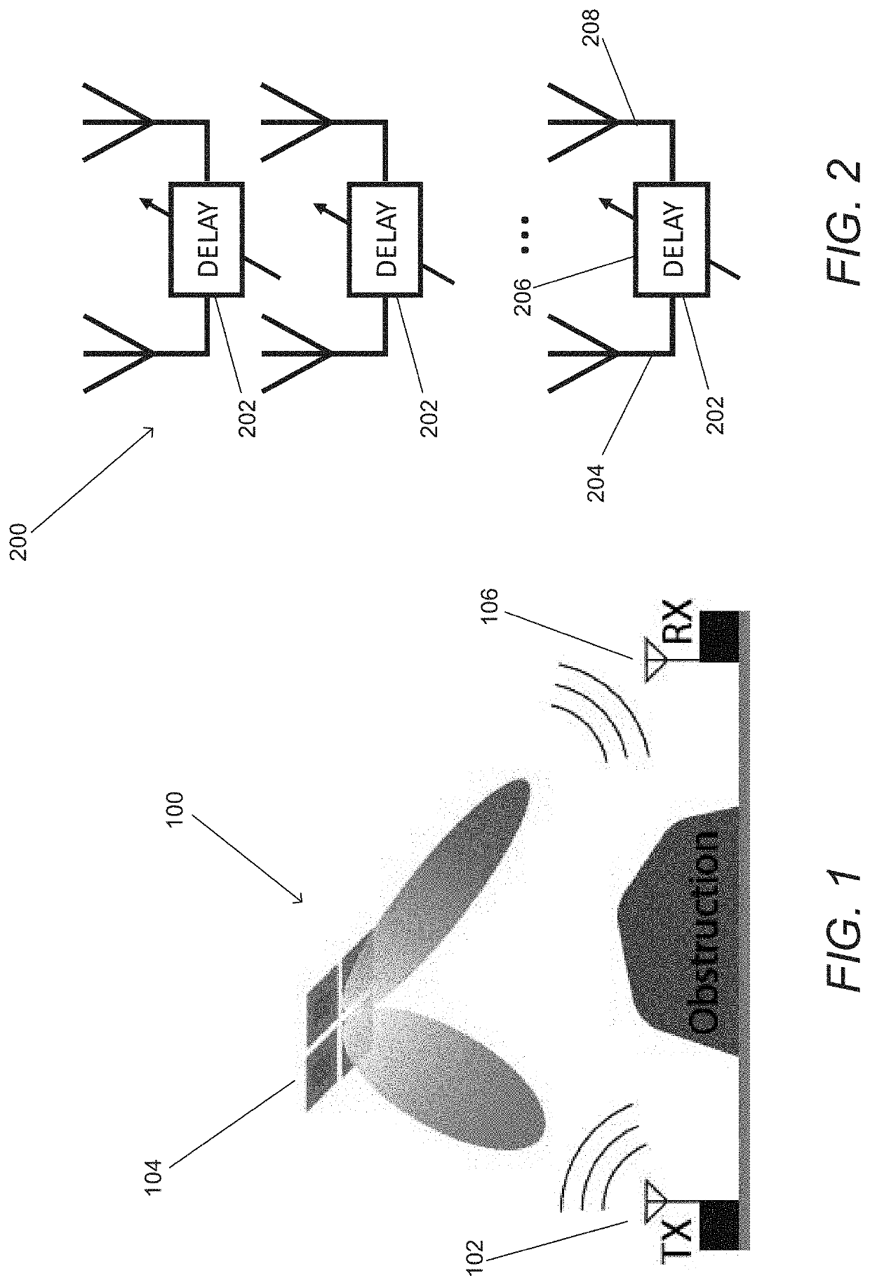
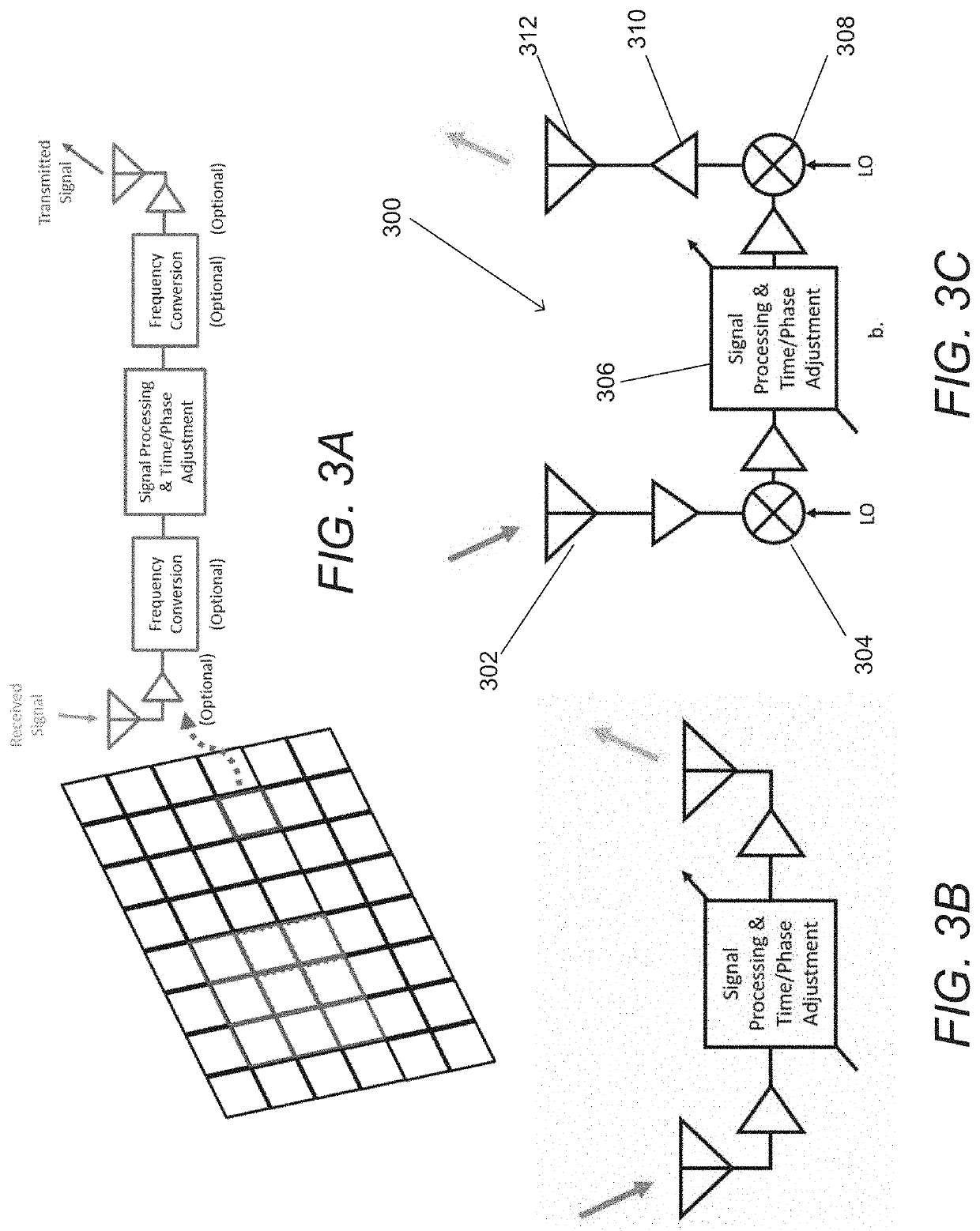
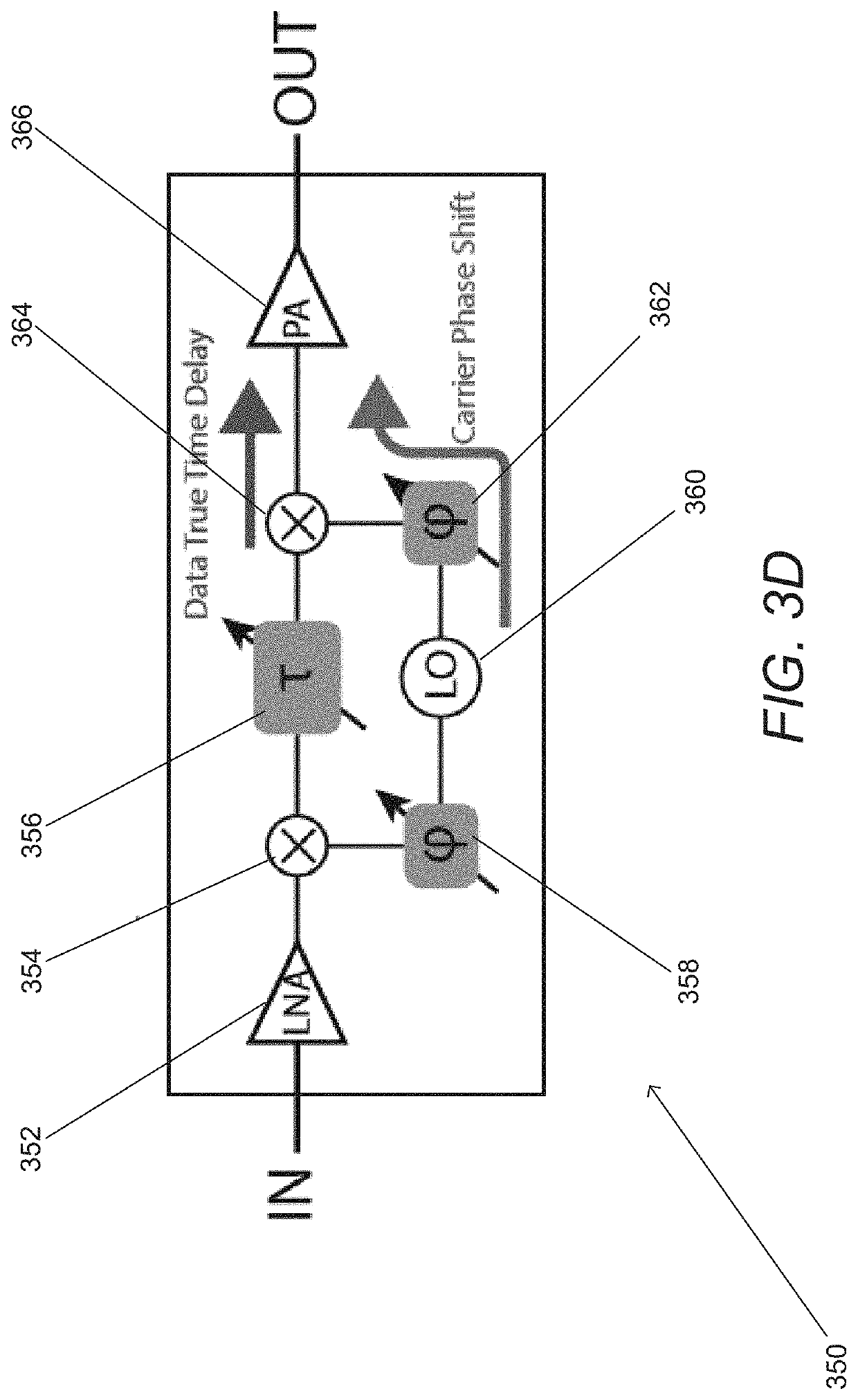
[0099]Turning now to the drawings, spatial redistributors and methods of redistributing signals in accordance with various embodiments of the invention are illustrated. In many embodiments of the invention, the spatial redistributors utilize time delay beamforming arrays to redistribute mm-wave signals. In a number of embodiments, the time delay beamforming arrays are decentralized, which means that they do not share a phase coherent reference signal. In many embodiments, the time delay beamforming arrays are constructed using an array of channels that coordinate by passing command and control information. The channels can be considered to be a signal path through a spatial redistributor connected to receive and / or transmit elements that are independent (i.e. signals from different channels are not combined within the spatial redistributor). Each channel can apply time and phase adjustments to a received signal. By coordinating the time and phase adjustments across an array of chann...


PUM


Abstract

Spatial redistributors and methods of redistributing signals in accordance with various embodiments of the invention are illustrated. One embodiment includes an array of channels configured to receive and retransmit a signal, where each of a plurality of independently operating channels in the array includes: at least one antenna element; an RF chain configured to apply at least a time delay to the received signal prior to retransmission; control circuitry configured to control the time delay applied to the received signal by the RF chain; and a reference oscillator. In addition, the array of channels is configured to redirect a signal received from a first set of directions for retransmission in a second set of directions; and the control circuitry of the channels in the array of channels coordinates the time delays applied to the received signal across the array of channels to control the wave front of the retransmitted signal.

Description

CROSS-REFERENCE TO RELATED APPLICATIONS[0001]The current application claims priority to U.S. Provisional Patent Application No. 62 / 783,011, entitled “Scalable, Agile, Electronically-Steering Conduit Array” and filed Dec. 20, 2018, U.S. Provisional Patent Application No. 62 / 897,764, entitled “Dynamic Scalable Decentralized Timed-Array Router” and filed Sep. 9, 2019 and U.S. Provisional Patent Application No. 62 / 931,634, entitled “Scalable Router Enhancements and Applications” filed Nov. 6, 2019. The disclosures of U.S. Provisional Patent Application Nos. 62 / 783,011, 62 / 897,764, and 62 / 931,634 are hereby incorporated by reference herein in their entireties.FIELD OF THE INVENTION[0002]The present invention generally relates to wireless communications and more specifically to the use of decentralized beam-forming systems and arrays to spatially redistribute mm-wave transmissions.BACKGROUND[0003]Over the last two decades, the development of mm-wave silicon ICs for communications and sens...

Claims


Application Information

Patent Timeline
Patent Type & Authority Applications(United States)
IPC IPC(8): H04B7/06H04B7/02H04L1/08
CPCH04B7/0697H04B7/0667H04B7/028H04L1/08H04B7/0617H04B7/15H04B7/086H04B7/15507
Inventor HAJIMIRI, SEYED ALIFIKES, AUSTIN C.KHIAL, PARHAM PORSANDEH
Owner CALIFORNIA INST OF TECH
Why Eureka
Try Eureka