Injection molding apparatus

a technology of injection molding and equipment, which is applied in the field of injection molding equipment, can solve the problems of increased installation space, increased installation cost, and difficulty to be described below, and achieve the effect of suppressing the cost increase of the gear-type reducer

Active Publication Date: 2020-07-02
NISSEI PLASTIC IND CO LTD
View PDF0 Cites 1 Cited by
  • Summary
  • Abstract
  • Description
  • Claims
  • Application Information

AI Technical Summary

Benefits of technology

[0048]By providing the shaft coupling therebetween, the output shaft of the geartype reducer...

Problems solved by technology

However, because the hydraulic pump is newly added, installation costs increase, and an installation space increases.
However, in a hydraulic injection molding device that is designed with a hydraulic motor, in order to replace the hydraulic motor to an electric motor, there are difficulties to be described below.
The continuously variable transmission has a complicated structure, and needs costs for maintenance service.
However, in the case of the general gea...

Method used


Image

  • Injection molding apparatus
  • Injection molding apparatus
  • Injection molding apparatus

Examples


Embodiment Construction

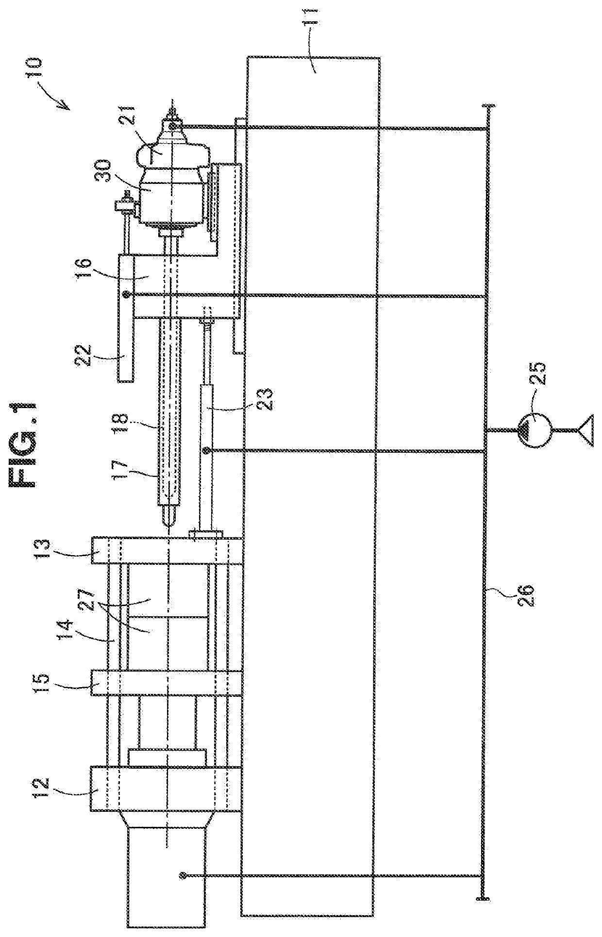
[0059]As illustrated in FIG. 1, a base hydraulic injection molding device 10 includes a bed 11, a mold clamping cylinder 12, a fixed mount 13, a tie bar 14, a movable mount 15, a moving mount 16, a heating cylinder 17, a screw 18, a screw driving unit 30, a hydraulic motor 21, an injecting cylinder 22, an injecting device moving cylinder 23, a hydraulic pump 25, and a hydraulic piping 26.

[0060]The mold clamping cylinder 12 and the fixed mount 13 are fastened to the bed 11.

[0061]The tie bar 14 is extended so as to connected to the mold clamping cylinder 12 and to the fixed mount 13.

[0062]The movable mount 15 is installed between the mold clamping cylinder 12 and the fixed mount 13 so as to be movable along the tie bar 14.

[0063]The moving mount 16 is mounted on the bed 11 so as to be movable outside the fixed mount 13.

[0064]The heating cylinder 17 is supported by the moving mount 16, and is extended toward the fixed mount 13.

[0065]The screw 18 is retained in the heating cylinder 17 so...


PUM

PropertyMeasurementUnit
Shapeaaaaaaaaaa
Torqueaaaaaaaaaa

Abstract

An injection molding apparatus is on the basis of a hydraulic injection molding device, and the apparatus includes an electric motor, a torque variable mechanism that changes output torque by the electric motor, and a screw driving unit that transmits the output torque by the torque variable mechanism to a screw. The screw is turned by the electric motor, the torque variable mechanism, and the screw driving unit. The torque variable mechanism applies, to the screw, torque equivalent to a hydraulic drive.

Description

FIELD OF THE INVENTION[0001]The present disclosure relates to an injection molding apparatus on the basis of a hydraulic injection molding device.BACKGROUND[0002]An injection molding apparatus includes main components that are a mold clamping device which clamps metal molds, and an injecting device that injects a resin material to a cavity in the clamped metal molds.[0003]A hydraulic injection molding device conventionally known is disclosed in JP H10-58508 A.[0004]A hydraulic injection molding device disclosed in, for example, JP H10-58508 A includes a hydraulic mold opening and closing device, a hydraulic motor that turns a screw, a hydraulic injecting cylinder that moves forward or backward the screw, and a hydraulic pump, etc.[0005]Moreover, another hydraulic injection molding device conventionally known is disclosed in, for example, JP H7-119041 A.[0006]The injection molding apparatus disclosed in JP H7-119041 A includes a hydraulic mold clamping cylinder, a hydraulic motor tha...

Claims


Application Information

Patent Timeline
IPC IPC(8): B29C45/50
CPCB29C45/5008B29C2045/506B29C2045/1794B29C45/17B29C2045/1792B29C2045/5048B29C45/83
Inventor UEHARA, TAKEMIOKUBO, KAZUYUKIHANDA, HIROYUKITOKIDA, SATORU
Owner NISSEI PLASTIC IND CO LTD
Why Eureka
Try Eureka