Wireless Power Transmission Using a Capacitive Sensor

a capacitive sensor and wireless technology, applied in the field of capacitive sensor, can solve problems such as the alignment of the receive coil, and achieve the effect of optimizing the capacitance of the receive coil and optimizing the power transfer

Active Publication Date: 2020-07-02
INTEGRATED DEVICE TECH INC
View PDF5 Cites 5 Cited by
  • Summary
  • Abstract
  • Description
  • Claims
  • Application Information

AI Technical Summary

Benefits of technology

[0009]According to some embodiments, a capacitor sensor can be part of a receiver or a transmitter. In some embodiments, the capacitor sensor uses the receive coil and rectifier circuitry. In power transfer operation, the rectifier circuitry rectifies the AC signal in the receive coil, and provides a rectified voltage on an output terminal. But in order to align the receive coil to the transmit coil, the receive coil and rectifier circuitry operation is reversed: the

Problems solved by technology

Ongoing issues with respect to wireless power transmission is the alignment of receive coils wit

Method used


Image

  • Wireless Power Transmission Using a Capacitive Sensor
  • Wireless Power Transmission Using a Capacitive Sensor
  • Wireless Power Transmission Using a Capacitive Sensor

Examples


Embodiment Construction

[0020]In the following description, specific details are set forth describing some embodiments of the present invention. It will be apparent, however, to one skilled in the art that some embodiments may be practiced without some or all of these specific details. The specific embodiments disclosed herein are meant to be illustrative but not limiting. One skilled in the art may realize other elements that, although not specifically described here, are within the scope and the spirit of this disclosure.

[0021]This description illustrates inventive aspects and embodiments should not be taken as limiting—the claims define the protected invention. Various changes may be made without departing from the spirit and scope of this description and the claims. In some instances, well-known structures and techniques have not been shown or described in detail in order not to obscure the invention.

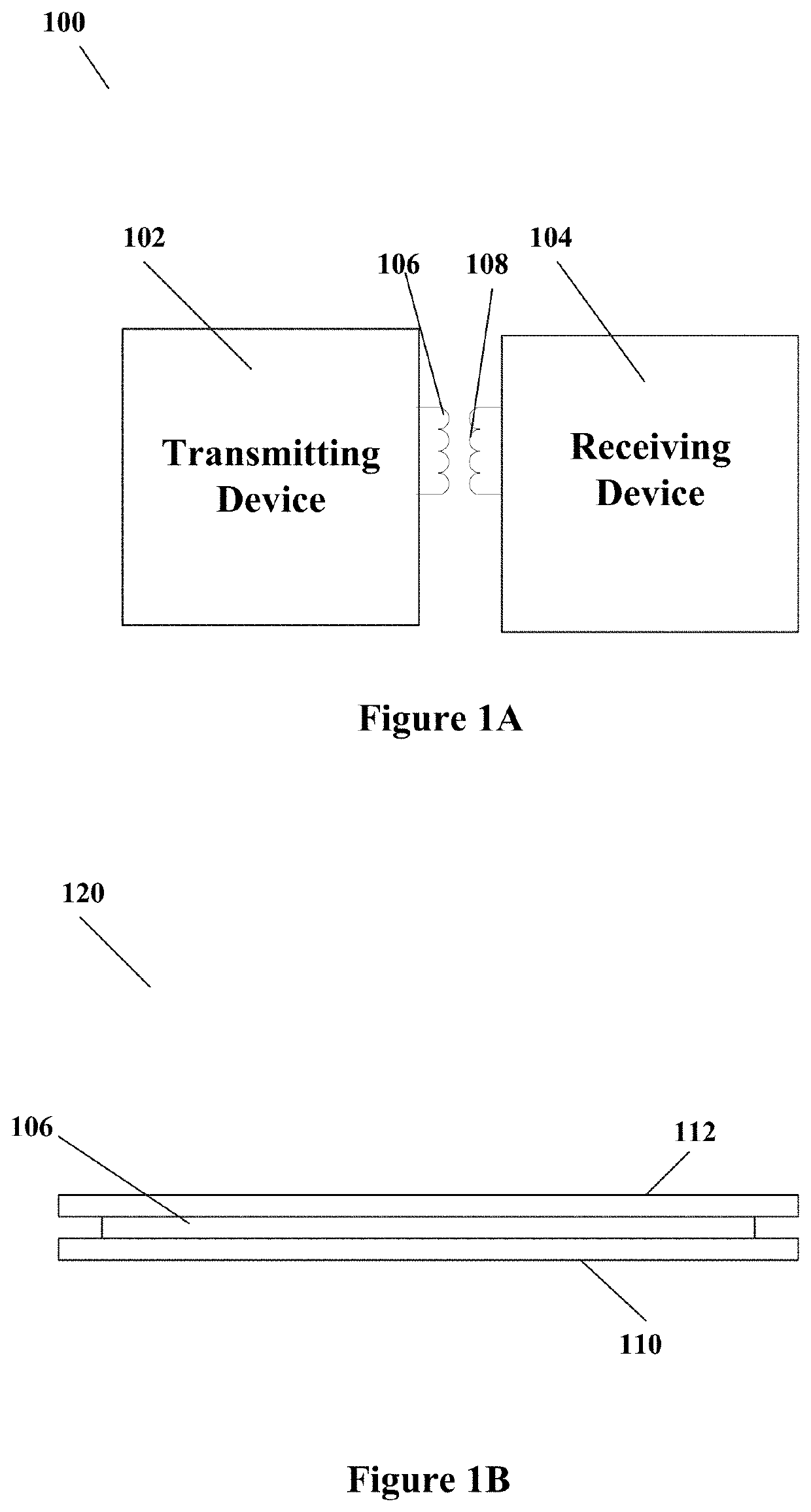
[0022]FIG. 1A illustrates an example wireless power transmission system 100. As illustrated in FIG. 1A,...


PUM


Abstract

A capacitor sensor array (or grid) over a wireless power transmission coil can include a first set of lines; a second set of lines intersecting the first set of lines; a first multiplexer coupled to provide a charge (e.g. in the form of a DC voltage) from a voltage source to the first set of lines and provide first signals to detect voltages on each line; and a second multiplexer coupled to provide a charge from the voltage source to the second set of lines and provide second signals to detect voltages on each line, wherein an object positioned with respect to the first set of lines and the second set of lines is located. According to some embodiments, a wireless power receive coil and a rectifier circuit can be used in forming a capacitor sensor, to sense the capacitance between the receive and transmit coils for better alignment between the two coils. Other embodiments are also provided.

Description

CROSS REFERENCE TO RELATED APPLICATIONS[0001]The present application claims priority to U.S. provisional patent application No. 62 / 787,553, filed on Jan. 2, 2019, incorporated herein by reference, and U.S. provisional patent application No. 62 / 786,200, filed on Dec. 28, 2018, incorporated herein by reference.TECHNICAL FIELD[0002]Embodiments of the present invention are related to wireless transmission of power and, in particular, to a capacitive sensor associated with the wireless power transmission.DISCUSSION OF RELATED ART[0003]Mobile devices, for example smart phones, tablets, wearables and other devices are increasingly using wireless power charging systems. In general, wireless power transfer involves a transmitter driving a transmit coil and a receiver with a receiver coil placed proximate to the transmit coil. The receiver coil receives the wireless power generated by the transmit coil and uses that received power to drive a load, for example to provide power to a battery cha...

Claims


Application Information

Patent Timeline
IPC IPC(8): H02J50/90H02J50/10H02J50/40H02J7/02H03K17/955
CPCH02J7/025H02J50/90H02J50/40H02J50/10H03K17/955H02J50/20H02J50/12H02J50/402H02J50/60H03K2217/96073G01R31/382
Inventor SMITH, NICHOLAUSLIU, RUIQI, TAOBAVISI, AMIT D.JEONG, CHAN YOUNG
Owner INTEGRATED DEVICE TECH INC
Why Eureka
Try Eureka