Aerosol or spray device, spray nozzle unit and method of manufacturing the same

a technology of spray device and spray nozzle, which is applied in the direction of medical devices, medical applicators, medical devices, etc., can solve the problems of not using glue, solvent or sealing agent, and no specific measure is known to guarantee a good liquid tight seal, so as to improve the strength, prevent the clogging of the spray nozzle, and improve the effect of sealing

Pending Publication Date: 2020-07-09
MEDSPRAY
View PDF8 Cites 0 Cited by
  • Summary
  • Abstract
  • Description
  • Claims
  • Application Information

AI Technical Summary

Benefits of technology

[0011]As the first rim sealingly engages a downstream surface of the nozzle plate and extends along a circumferential edge of the downstream surface of the nozzle plate, it operates as a sort of O-ring, whereby a force of the pressurized liquid in operation presses the nozzle plate against the rim so as so seal the nozzle plate thus prevent liquid from leaking around the nozzle plate.
[0080]The spray nozzle plate (the most downstream, the one closest to and spraying into the outside world) may be used to incorporate an over-pressure safety feature. E.g. a larger orifice which is covered by the plastic housing may be created as a well defined breaking point in the system. There a leak may be introduced at overpressure, reducing the risk that silicon fragments are launched towards the patient's eyes in case of an eye spray device or into the lungs, in case of an inhaler device.

Problems solved by technology

It is known in the art to use a thin rim on the downstream side to fixate mechanically the nozzle plate, however no specific measure is known to guarantee a good liquid tight seal without the use of glue, solvent or sealing agent.

Method used


Image

  • Aerosol or spray device, spray nozzle unit and method of manufacturing the same
  • Aerosol or spray device, spray nozzle unit and method of manufacturing the same
  • Aerosol or spray device, spray nozzle unit and method of manufacturing the same

Examples


Embodiment Construction

:

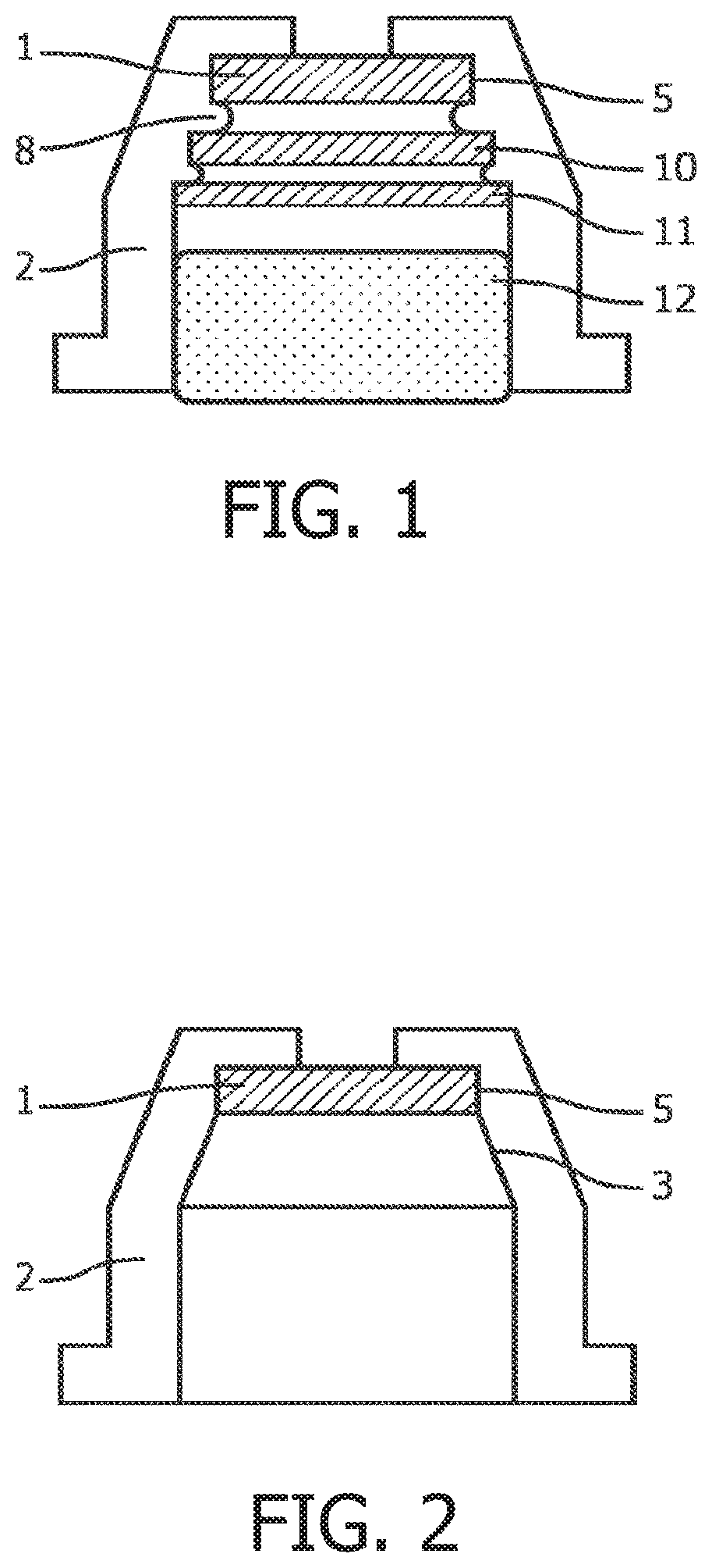
[0111]FIG. 1 shows a part of an aerosol generator according to a potential embodiment of the invention with three orifice plates (1, 10 and 11) and a sintered porous plastic pre filter (12). A spray nozzle orifice plate (1) is mounted in a thermoplastic holder (2). A second orifice plate (10) and a third orifice plate (11) are being mounted with heat and pressure, thus locally thermoplastically deforming the tapered seat wall (5), creating rivet-like flanges (8). These two orifice plates form a last chance filter (orifice plate 10), preferably with orifices which are half the diameter of the spray pore diameter in the spray nozzle orifice plate (1), and a pre filter (orifice plate 11) with larger orifices than the last chance filter. A sintered porous plastic pre filter (depth filter 12) is mounted and is being kept in place by a simple press fit.

[0112]FIG. 2 shows an embodiment of the invention with one orifice plate (1) mounted in a thermoplastic holder (2). The holder (2) is pro...


PUM

PropertyMeasurementUnit
elevated temperatureaaaaaaaaaa
thicknessaaaaaaaaaa
thicknessaaaaaaaaaa

Abstract

A method for manufacturing an spray device includes assembling at least one spray nozzle plate into a thermoplastic holder, while controlling the temperature of the spray nozzle plate and / or the holder and as a result at least locally plastically deforming the holder permanently. After the thermoplastic deformation of a seat of the holder, a diameter of the seat of the holder upstream of the spray nozzle plate exceeds a diameter of the seat of the holder downstream of the nozzle plate. The thermoplastic holder may have a tapered seat, where the smallest cross section of the tapered seat is smaller than the spray nozzle plate, where a widest side of the tapered seat is pointing towards a supply side of the liquid.

Description

CROSS-REFERENCE TO RELATED APPLICATIONS:[0001]This application is a Divisional of U.S. application Ser. No. 15 / 320,371, filed Dec. 20, 2016, which is the National Stage of International Application No. PCT / NL2015 / 050455 filed Jun. 19, 2015, which claims the benefit of Netherlands Application No. NL 2013044, filed Jun. 20, 2014, the contents of which is incorporated by reference herein.FIELD OF THE INVENTION:[0002]The invention describes a spray device for generation of a fine spray, a spray nozzle unit, comprising a spray nozzle plate and methods of manufacturing the same.BACKGROUND OF THE INVENTION:[0003]Micro spray nozzle plates with orifices of a few micrometers or smaller, created by means of semiconductor manufacturing techniques, need to be packaged for connection to e.g. a spray pump or syringe according to pharmaceutical manufacturing protocols. Liquids, to be sprayed through spray nozzles with small orifices, often require the use of one, or a series of prefilter plates to ...

Claims


Application Information

Patent Timeline
Patent Type & Authority Applications(United States)
IPC IPC(8): A61M11/00B05B15/40B05B1/14B05B1/16
CPCB05B15/40B05B1/169A61M2207/00A61M11/003B05B1/14A61M11/006A61M11/007A61M35/00B29C53/84B29C65/568
Inventor VAN EGMOND, HENRIDE KRUIJF, WILHELMUS PETRUS JOHANNESNIJDAM, WIETZEWISSINK, JEROEN MATHIJNVAN RIJN, CORNELIS JOHANNES MARIA
Owner MEDSPRAY
Why Eureka
Try Eureka