In-line pressure accumulator and flow-control system for biological or chemical assays

a flow control system and pressure accumulator technology, applied in the direction of instruments, material analysis, etc., can solve the problems of increasing the likelihood of degasification, increasing the pressure of the fluid at the reagent reservoir, and limiting the speed at which the fluid may be delivered to the flow cell, so as to achieve the effect of changing the operating volume of the interior

Active Publication Date: 2020-07-23
ILLUMINA INC
View PDF4 Cites 2 Cited by
  • Summary
  • Abstract
  • Description
  • Claims
  • Application Information

AI Technical Summary

Benefits of technology

[0005]In an embodiment, a flow-control system is provided that includes a fluid reservoir configured to store a fluid, a pressure accumulator in flow communication with and positioned downstream from the fluid reservoir, and a loading zone that is configured to receive and fluidly couple to a flow cell having a biological or chemical sample. The loading zone is in flow communication with and positioned downstream from the pressure accumulator. The flow-control system also includes a system pump in flow communication with and positioned downstream from the loading zone. The system pump is configured to induce a flow of the fluid from the fluid reservoir and through the pressure accumulator and the loading zone. The pressure accumulator includes a wall actuator and an interior chamber that is defined by a movable chamber wall and has an operating volume. The wall actuator is configured to move the chamber wall and thereby change the operating volume of the interior chamber. The pressure accumulator is configured to receive fluid into the interior chamber from the fluid reservoir during a filling operation. The wall actuator is configured to move the chamber wall to impart pressure on the fluid and drive the fluid toward the loading zone during a pressure-assist operation.

Problems solved by technology

One challenge for flow-control systems that carry out designated protocols, such as the SBS protocol described above, is that the speed at which the fluid may be delivered to the flow cell is limited by system resistances.
Moreover, increasing the flow rate of the fluids may cause a pressure drop that increases the likelihood of degasification, which may be undesirable for certain applications.
However, increasing the pressure of the fluid at the reagent reservoir can be challenging due to the volume of the fluid in the reservoir.
Moreover, the increased pressure may risk gassing the fluid (i.e., introducing external air into the fluid at the reagent reservoir).

Method used


Image

  • In-line pressure accumulator and flow-control system for biological or chemical assays
  • In-line pressure accumulator and flow-control system for biological or chemical assays
  • In-line pressure accumulator and flow-control system for biological or chemical assays

Examples


Embodiment Construction

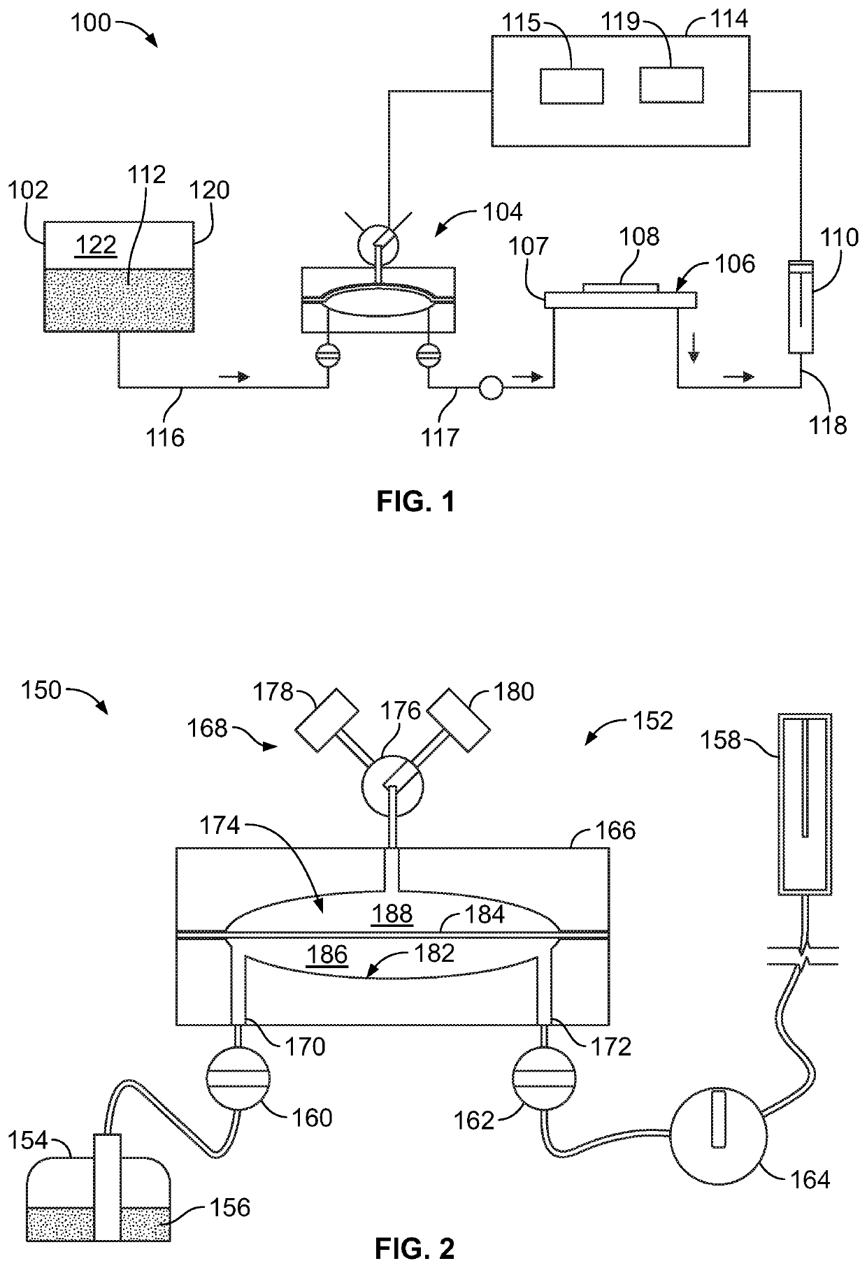
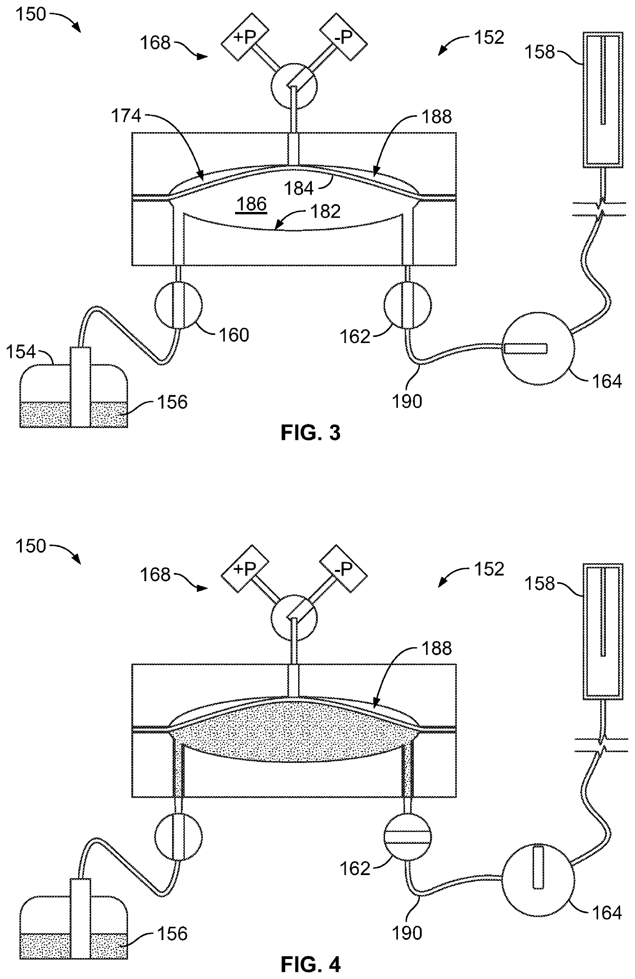
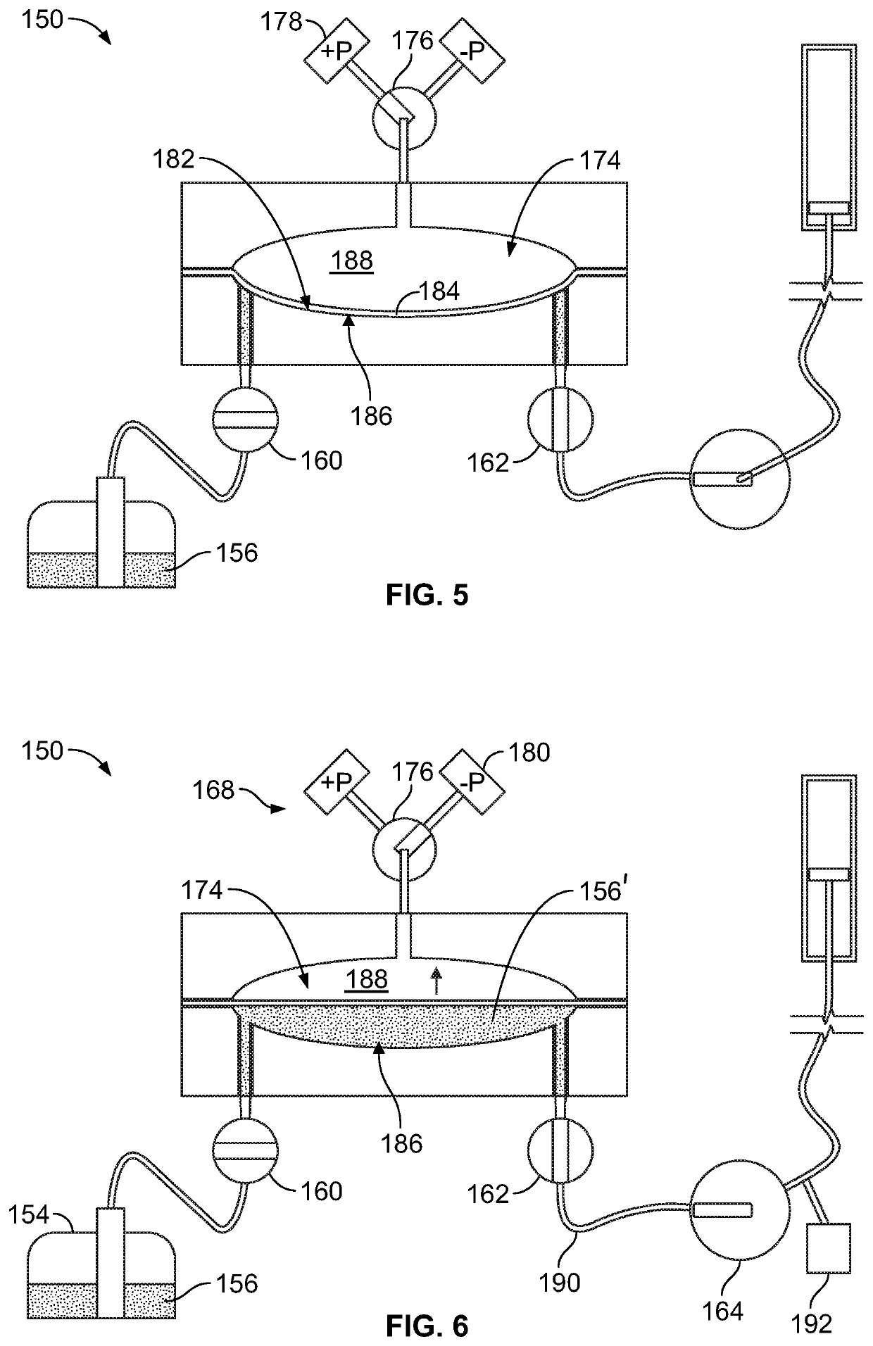
[0051]Embodiments set forth herein include pressure accumulators, flow-control systems having pressure accumulators, and methods that utilize pressure accumulators. The pressure accumulator is fluidly disposed between a fluid reservoir, such as a reagent reservoir, and a system pump. The system pump is configured to induce the flow of fluid through the flow-control system. The pressure accumulator is configured to (a) offset a pressure drop in fluidic line(s) of the system between the pressure accumulator and the system pump; (b) maintain the pressure in the fluidic line(s); and / or (c) increase the pressure in the fluidic line(s). As such, the pressure accumulator may enable faster reagent delivery to flow cells compared to other known systems. Decreasing the time for reagents to arrive to the flow cell may decrease the time for each cycle. As described above, sessions (e.g., sequencing runs) typically include numerous cycles (e.g., tens, hundreds, or thousands). Accordingly, if the...


PUM

PropertyMeasurementUnit
volumeaaaaaaaaaa
operating volumeaaaaaaaaaa

Abstract

Flow-control system includes a fluid reservoir configured to store a fluid, a pressure accumulator in flow communication with and positioned downstream from the fluid reservoir, and a loading zone that is configured to receive and fluidly couple to a flow cell having a biological or chemical sample. The loading zone is in flow communication with and positioned downstream from the pressure accumulator. The flow-control system also includes a system pump in flow communication with and positioned downstream from the loading zone. The system pump is configured to induce a flow of the fluid from the fluid reservoir and through the pressure accumulator and the loading zone. The pressure accumulator is configured to receive fluid from the fluid reservoir during a filling operation. The pressure accumulator is configured to impart pressure on the fluid and drive the fluid toward the loading zone during a pressure-assist operation.

Description

CROSS-REFERENCE TO RELATED APPLICATION[0001]The present application claims the benefit of U.S. Provisional Application No. 62 / 209,040, which was filed on Aug. 24, 2015 and is incorporated herein by reference in its entirety.BACKGROUND[0002]Embodiments of the present application relate generally to systems and method for controlling flow of a fluid through a system configured for biological or chemical analysis of a sample or configured for sample preparation.[0003]Various assay protocols used for biological or chemical research are concerned with performing a large number of controlled reactions. In some cases, the controlled reactions are performed on a flow cell. The flow cell may have, for example, inlets, outlets, and a plurality of channels extending therebetween. Reagents may be delivered to the flow cell in order to carry out the designated reactions. The designated reactions may then be observed and analyzed to help identify properties or characteristics of the chemicals inv...

Claims


Application Information

Patent Timeline
Patent Type & Authority Applications(United States)
IPC IPC(8): G01N35/10G01N35/00
CPCG01N35/0092G01N35/1097G01N35/1095
Inventor STONE, MICHAEL J.DREWS, BRADWILLIAMSON, ERIK
Owner ILLUMINA INC
Why Eureka
Try Eureka