Method and control unit for operating a transmission

a transmission and control unit technology, applied in the direction of multiple ratio transmissions, mechanical equipment, transportation and packaging, etc., can solve the problems of adversely affecting the overall efficiency of an automatic transmission to an undesirable extent, drag torques that affect the overall efficiency of the transmission, and the form-locking shift element may not be transferrable into its disengaged operating condition, etc., to achieve short operating times, reduce hydraulic pressure, and increase torque at the shift element

Active Publication Date: 2021-03-30
ZF FRIEDRICHSHAFEN AG
View PDF9 Cites 0 Cited by
  • Summary
  • Abstract
  • Description
  • Claims
  • Application Information

AI Technical Summary

Benefits of technology

[0024]Moreover, the threshold value of the deviation represents a limiting value, above which there is just enough time to prevent the shift element from engaging in the undesirable automatic operating condition change into its disengaged operating condition or into its engaged operating condition, with the aid of appropriate countermeasures.
[0030]This means, the countermeasure preventing the undesirable operating condition change was triggered already during an existing positive engagement between the shift-element halves and prevents the undesirable operating condition change of the form-locking shift element.
[0034]Additionally, in the presence of a hydraulic pressure greater than the threshold value and upon detection of a flank jamming, the hydraulic pressure is increased and / or a torque present at the shift element is reduced. This approach offers the advantage of transferring the form-locking shift element into the demanded engaged operating condition or into the disengaged operating condition within short operating times.
[0036]Alternatively, the form-locking shift element may be transferred, by establishing an operating condition of the transmission, into an operating condition that is unloaded in such a way that the form-locking shift element can be transferred into its disengaged operating condition or into its engaged operating condition as demanded. For this purpose, for example, a ratio may be engaged in the transmission, for the implementation of which the form-locking shift element is not located in the power flow of the transmission and an engagement of the form-locking shift element also does not cause a preloading of the transmission.
[0044]With the aid of the control unit, an undesirable operating condition change of the form-locking shift element is detected as early as possible and a countermeasure counteracting the undesirable operating condition change is triggered. Therefore, undesirable operating conditions of a transmission are very likely avoided.

Problems solved by technology

Disadvantageously, however, friction-locking shift elements in the disengaged operating condition cause drag torques, which adversely affect an overall efficiency of an automatic transmission to an undesirable extent.
Drag torques adversely affect the overall efficiency of a transmission.
Due to an excessively rapid or faulty build-up of the torque applied at the form-locking shift element, or due to a faulty reduction of the applied torque, the form-locking shift element may not be transferrable into its disengaged operating condition.
However, the static friction between the flanks of the dog elements of the shift-element halves, which are resting against one another, is so high that the engagement force acting on the shift elements in the engagement direction is not sufficient to overcome the static friction and completely engage the form-locking shift element.
This means, the actuating pressure of the shift elements of a transmission is also reduced and a current operating condition of the transmission may not be maintainable to the demanded extent during unfavorable operating conditions.
If such a transmission does not include hydraulic protection in the form of a hydraulic accumulator or an electrical auxiliary pump, it is possible that, in particular, form-locking shift elements disengage to an undesirable extent or transition into an engaged operating condition.
The values of the sensor signal have a non-negligible scattering, which does not allow for a precise determination of a current dog position.

Method used


Image

  • Method and control unit for operating a transmission
  • Method and control unit for operating a transmission
  • Method and control unit for operating a transmission

Examples


Embodiment Construction

[0056]Reference will now be made to embodiments of the invention, one or more examples of which are shown in the drawings. Each embodiment is provided by way of explanation of the invention, and not as a limitation of the invention. For example, features illustrated or described as part of one embodiment can be combined with another embodiment to yield still another embodiment. It is intended that the present invention include these and other modifications and variations to the embodiments described herein.

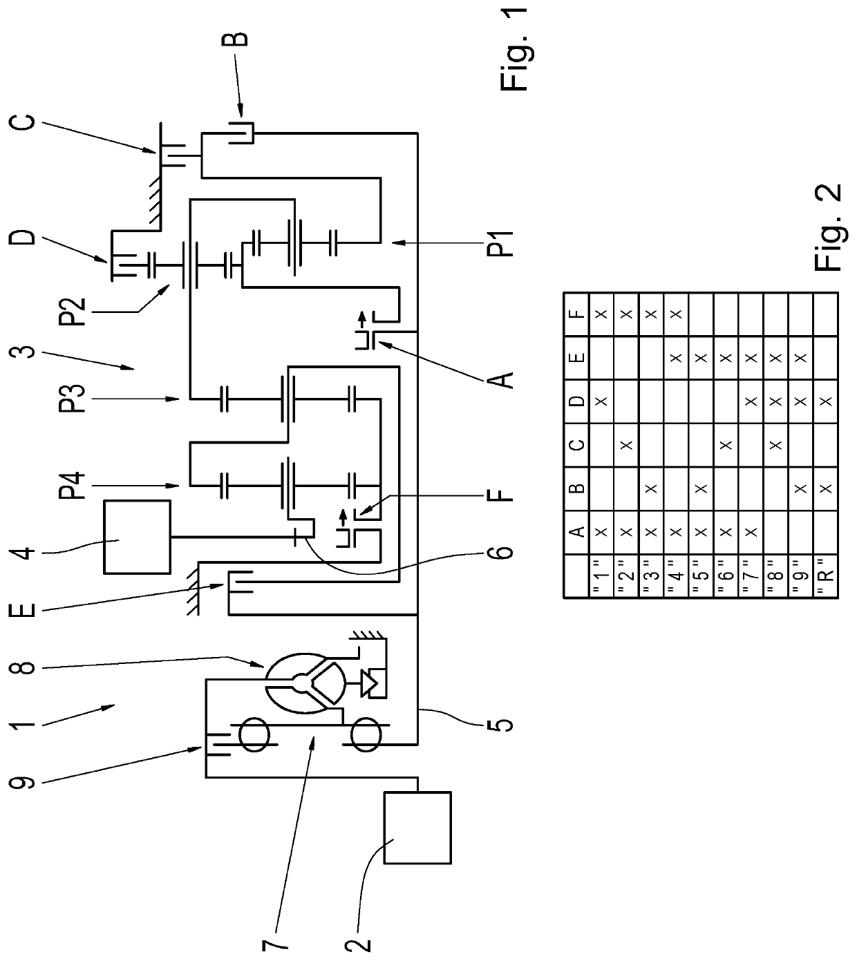
[0057]FIG. 1 shows a schematic of a vehicle drive train 1 including a prime mover 2, a transmission 3, and a driven end 4. The prime mover 2 is an internal combustion engine in this case. The transmission 3 is an automatic transmission, in which multiple gears “1” through “9” for forward travel and at least one gear “R” for travel in reverse are implementable. Depending on the particular configuration of the vehicle drive train 1, the driven end 4 includes one, two, or more drivab...


PUM


Abstract

A method for operating a transmission (3) is provided, which includes a hydraulic pump drivable on a transmission-input end and at least one form-locking shift element (A, F). One of the shift-element halves is displaceable between a first end position and a second end position with a hydraulic pressure of the hydraulic pump. The current position of the shift-element half is detected with a sensor and is stored as a specified end-position value if the shift-element half is located in one of the end positions, the hydraulic pump is driven, and the shift-element half is actuated, with the hydraulic pressure, towards the current end position. When the hydraulic pressure is less than a threshold value, a deviation is determined between the current position of the shift-element half and the specified end-position value. The hydraulic pressure is increased when the deviation is greater than a threshold value.

Description

CROSS-REFERENCE TO RELATED APPLICATION[0001]The present application is related and has right of priority to German Patent Application No. 10 2018 220 868.9 filed on Dec. 3, 2018, the entirety of which is incorporated by reference for all purposes.FIELD OF THE INVENTION[0002]The invention relates generally to a method for operating a transmission. Moreover, the invention relates generally to a control unit for carrying out the method as well as to a corresponding computer program product.BACKGROUND[0003]DE 10 2005 002 337 A1 describes an eight-speed multi-stage transmission that includes friction-locking shift elements. The shift elements are multi-disk clutches or multi-disk brakes. In the presence of a shift request for a ratio change in the transmission, at least one of the friction-locking shift elements is to be disengaged from the power flow of the transmission device and at least one further friction-locking shift element is to be engaged into the power flow of the transmissio...

Claims


Application Information

Patent Timeline
Patent Type & Authority Patents(United States)
IPC IPC(8): F16H61/02F16H61/16
CPCF16H61/0265F16H61/16F16H2200/0065F16H2200/2012F16H2200/2046F16H2708/20F16H2710/04F16H2710/20F16H61/0204F16H63/42F16H61/40F16H59/68F16H2059/6823F16H61/0025F16H61/686
Inventor JEHLE, MARTINASCHMIDT, ANDREASSCHWIMMER, ANGELIQUEPANNEK, CHRISTIANZERLAUT, DANIEL
Owner ZF FRIEDRICHSHAFEN AG
Why Eureka
Try Eureka