Moving body image generation recording display device and program product

a body image and recording technology, applied in image generation, instruments, image rendering, etc., can solve the problem that the target cannot be displayed in some cases, and achieve the effect of reducing storage capacity and being easy to understand

Active Publication Date: 2020-07-23
KAGA FEI CO LTD
View PDF0 Cites 4 Cited by
  • Summary
  • Abstract
  • Description
  • Claims
  • Application Information

AI Technical Summary

Benefits of technology

[0018]The disclosed technique can provide information in a form easier to understand when an environment around a host moving body is displayed as a video and record a travel state of the moving body with a smaller storage capacity.

Problems solved by technology

Accordingly, when a target of image capturing is temporarily blocked by another moving body or moves to a blind spot of the camera, this target cannot be displayed in some cases.

Method used


Image

  • Moving body image generation recording display device and program product
  • Moving body image generation recording display device and program product
  • Moving body image generation recording display device and program product

Examples


Embodiment Construction

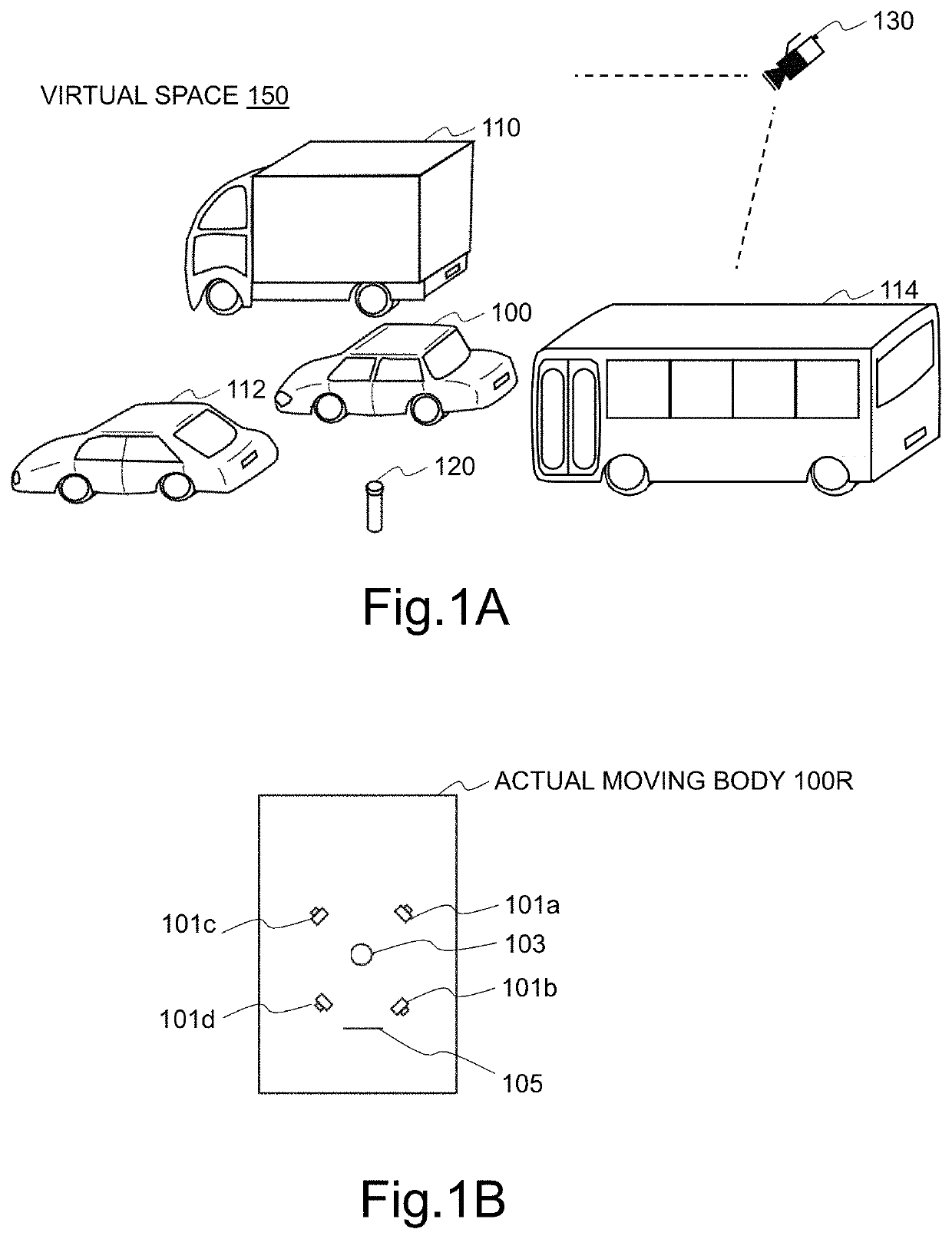
[0027]FIGS. 1A and 1B are a view illustrating examples of a virtual space and sensors installed in an actual moving body in one embodiment.

[0028]A virtual space 150 illustrated in FIG. 1A is constructed based on information such as video information on peripheral objects sent from cameras (101a to 101d) installed in an actual moving body 100R illustrated in FIG. 1B, information on relative speed, positions, and the like of the peripheral objects obtained by a radar 103, information of GPS received by a radio antenna 105, various kinds of information sent from other systems connected to a radio network, and information on the actual moving body 100R obtained from sensors (not illustrated) such as a speedometer, an accelerometer, and a gyroscope installed in the moving body 100R.

[0029]The cameras (101a to 101d), the radar 103, the radio antenna 105, and the sensors (not illustrated) such as the speedometer described above are examples and other appropriate information gathering device...


PUM


Abstract

A moving body position information recognition display device includes a traveling state obtaining part for obtaining information on a traveling state of a host moving body. An object information obtaining part for obtaining information on a plurality of objects including a shape of a travel road and another moving body. A virtual space construction part for constructing a virtual space by associating at least the host moving body and each of the plurality of objects with each of a plurality of virtual models and by arranging the associated virtual models in a three-dimensional space. A two-dimensional video generation part for generating a two-dimensional video capturing the virtual space from a virtual camera arranged in the virtual space and output the two-dimensional video. The two-dimensional video generation part generates the two-dimensional video while adding a predetermined effect to the virtual model corresponding to the object in the two-dimensional video.

Description

CROSS-REFERENCE TO RELATED APPLICATION[0001]This is a Continuation Application of PCT Application No. PCT / JP2018 / 036758 filed Oct. 1, 2018, which was not published under PCT Article 21 (2) in English.[0002]This application is based on and claims priority from the prior Japanese Patent Application No. 2017-192431 filed on Oct. 2, 2017, the entire disclosure of which and the above PCT Application are herein incorporated by reference.TECHNICAL FIELD[0003]The present invention relates to a device which generates an image of an object in a periphery of a moving body to record or display the image and to a program for performing such operations.BACKGROUND ART[0004]There is an image conversion technique in which images captured by using cameras installed in a moving body such as an automobile are processed and converted to images similar to images of the moving body as viewed from various directions. There is a technique such as so-called “around view monitor” (registered trademark) in whi...

Claims


Application Information

Patent Timeline
Patent Type & Authority Applications(United States)
IPC IPC(8): G06T19/00G06K9/00G06T15/08
CPCG06T15/08G06K9/00798G06K9/00825G06T2200/24G06T19/003H04N7/18G06T13/20G07C5/00G06T2215/16G06T2210/62G06T15/20G06T2210/61G06T19/00G08G1/166G06T15/503G06T19/006G06V20/584G06V20/588
Inventor FUEKI, KAZUMASATAKAHASHI, NOBORU
Owner KAGA FEI CO LTD
Why Eureka
Try Eureka