Beverage Brewing Device
a technology of brewing device and tea leaf basket, which is applied in the direction of tea extraction, domestic vessels, kitchen equipment, etc., can solve the problems of complex structure of transmission mechanism, inconvenient use, and inability to move up and down, and achieves flexible and rapid lifting of tea leaf baskets, low cost, and simple structure
- Summary
- Abstract
- Description
- Claims
- Application Information
AI Technical Summary
Benefits of technology
Problems solved by technology
Method used
Image
Examples
first embodiment
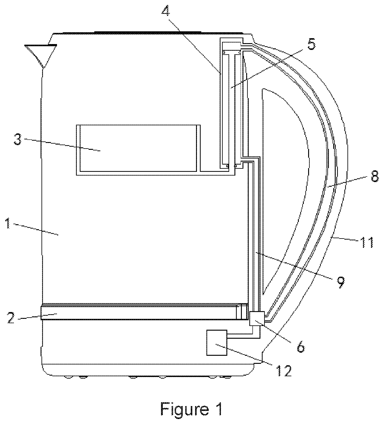
[0020]In the present disclosure, as shown in FIG. 1, the output end of the air pump 12 is connected to an electronic pressure relief valve 6, and the output end of the electronic pressure relief valve 6 is connected to a first air pipe 8 and a second air pipe 9 in parallel, wherein the first air pipe 8 and the second air pipe 9 are respectively connected to the first end and the second end of the air cylinder mechanism 4. When tea-leaves need to be replaced or added into the tea-leaf basket 3, the tea-leaf basket 3 needs to be lifted to the upper end of the kettle body 1. At this point, the air pump 12 is initiated to convey a driving gas, the electronic pressure relief valve 6 allows the second end of the air cylinder mechanism 4 to be communicated with the output end of the air pump 12, and allows the first end of the air cylinder mechanism 4 to be communicated with the pressure relief end of the electronic pressure relief valve 6. In this way, the driving gas enters the second en...
second embodiment
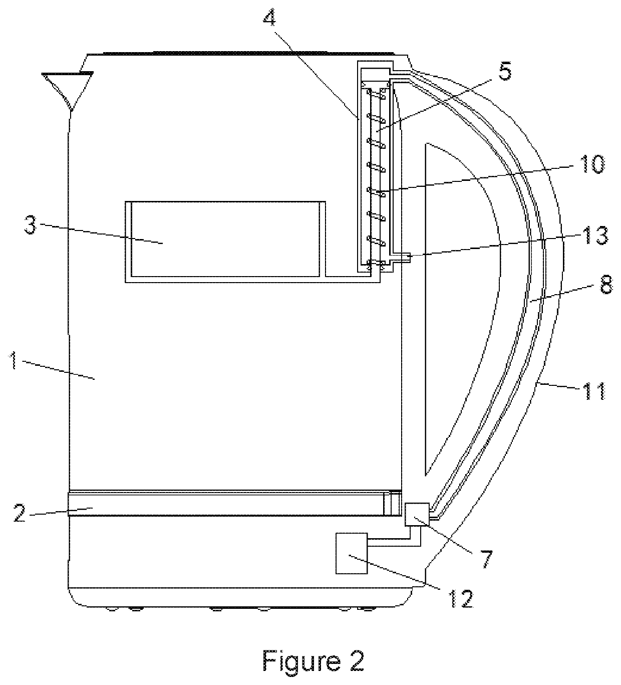
[0021]In the present disclosure, as shown in FIG. 2, the output end of the air pump 12 is connected to a pressure relief valve 7, and the output end of the pressure relief valve 7 is connected to the first end of the air cylinder mechanism 4 through the first air pipe 8. The second end of the air cylinder mechanism 4 is provided with an exhaust port, and the piston 5 is connected to a return spring 10. When tea-leaves need to be replaced or added to the tea-leaf basket 3, the tea-leaf basket 3 is required to be lifted to the upper end of the kettle body 1. At this point, the air pump 12 does not operate and the pressure relief valve 7 is turned on. In this way, the piston 5 moves upward under the action of the return spring 10. Meanwhile, the gas at the first end of the air cylinder mechanism 4 is discharged from the first air pipe 8 and the pressure relief valve 7, while the exhaust port 13 connected to the second end of the air cylinder mechanism 4 receives a gas, thereby balancin...
third embodiment
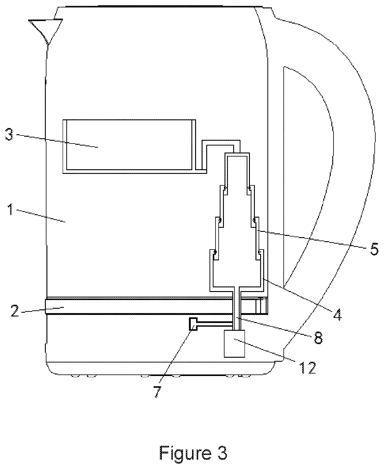
[0022]In the present disclosure, as shown in FIG. 3, the output end of the air pump 12 is connected to the lower end of the air cylinder mechanism 4 through a first air pipe 8, the piston 5 is telescopically moved via the upper end of the air cylinder mechanism 4, and a pressure relief valve 7 is connected to the first air pipe 8 in parallel. When tea-leaves need to be replaced or added into the tea-leaf basket 3, the tea-leaf basket 3 needs to be lifted to the upper end of the kettle body 1. At this point, the air pump 12 is initiated to convey a driving gas, and the pressure relief valve 7 is turned off, allowing the lower end of the air cylinder mechanism 4 to be communicated with the output end of the air pump 12. Thus, the driving gas enters the lower end of the air cylinder mechanism 4 from the first air pipe 8, and the piston 5 moves upward under the action of the air pressure. For being propelled by the piston 5, the tea-leaf basket 3 is lifted, allowing tea-leaves to be rep...
PUM
 Abstract
Description
Claims
Application Information
 - R&D
- Intellectual Property
- Life Sciences
- Materials
- Tech Scout
- Unparalleled Data Quality
- Higher Quality Content
- 60% Fewer Hallucinations
Browse by: Latest US Patents, China's latest patents, Technical Efficacy Thesaurus, Application Domain, Technology Topic, Popular Technical Reports.
© 2025 PatSnap. All rights reserved.Legal|Privacy policy|Modern Slavery Act Transparency Statement|Sitemap|About US| Contact US: help@patsnap.com


