Subcarrier diversity in optical communication systems

a technology of optical communication system and carrier, applied in the field of optical communication system, can solve the problems of violation of service level agreement, affecting the transmission rate of data in optical network, and inevitably exposed failures of data transmission, so as to achieve the effect of reducing the transmission rate and facilitating the operation

Active Publication Date: 2020-07-30
XIEON NETWORKS SARL
View PDF10 Cites 4 Cited by
  • Summary
  • Abstract
  • Description
  • Claims
  • Application Information

AI Technical Summary

Benefits of technology

[0049]In a preferred embodiment of the invention, each of the at least n light sources can emit light at each of the n wavelengths of the super channel. As will become more apparent from an exemplary embodiment described below, this way the redirection of part of the datastream can be easily effected by appropriate wavelength control of the light sources.
[0050]According to a preferred embodiment of the invention, the transmitting arrangement further comprises one or more additional light sources, wherein each additional light source can emit light at each of the n wavelengths of the super channel. The one or more additional light sources are “additional” in the sense that they are not used for transmitting the data stream under normal operating conditions, i.e. in the absence of disturbances causing the performance to drop below the predetermined performance threshold. Hence the transmitter comprises a number of light sources greater than the number n of wavelengths of the super channel. This allows reducing the transmission rate of some of the individual carriers, in particular the edge carriers, while still transmitting the data stream as a whole with the same data rate.

Problems solved by technology

The transmission of data in optical networks is inevitably exposed to failures that might affect the correct transmission of the data between nodes of the optical network.
Such failures may for example be due to transmission fiber impairment, for example due to fiber aging or degradation, nonlinear fiber effects, optical equipment impairment, such as filter drift, optical component aging or outage due to polarization related effects.
Further sources of failure can be due to the influence of external factors, such as weather conditions, seismic movements and the like, fiber repair or other kind of maintenance work in the optical network, or negligent human operation.
However, optical paths exclusively used as a backup, also referred to as protection paths in the art, typically have worse optical characteristics than the working path used under normal working conditions.
Consequently, the alternative optical path available in a particular failure situation may not be able to allow transmitting all of the data affected by the failure and hence lead to a violation of the service level agreement.
Moreover, in most cases it will be infeasible to provide “protection” for any path by having a dedicated restoration path on reserve (also referred to as “1+1 protection” in the art), due to lack of available link resources and the operational costs of associating a backup link for every connection.
However, finding a suitable restoration path will take some time (also referred to as “switch over time” in the art), and until the restoration path is found and established, a significant amount of traffic will be delayed or even lost.
Moreover, in many cases the restored path will have conditions completely different from the working path, and it may turn out that the restored path does not allow to make up for the full traffic of the previous working path.
Finally, in some cases it will turn out that no suitable restoration part can be found, such that further intervention may become necessary to reduce the throughput.

Method used


Image

  • Subcarrier diversity in optical communication systems
  • Subcarrier diversity in optical communication systems
  • Subcarrier diversity in optical communication systems

Examples


Embodiment Construction

[0067]For the purposes of promoting an understanding of the principles of the invention, reference will now be made to a preferred embodiment illustrated in the drawings, and specific language will be used to describe the same. It will nevertheless be understood that no limitation of the scope of the invention is thereby intended, such alterations and further modifications in the illustrated apparatus and such further applications of the principles of the invention as illustrated therein being contemplated as would normally occur now or in the future to one skilled in the art to which the invention relates.

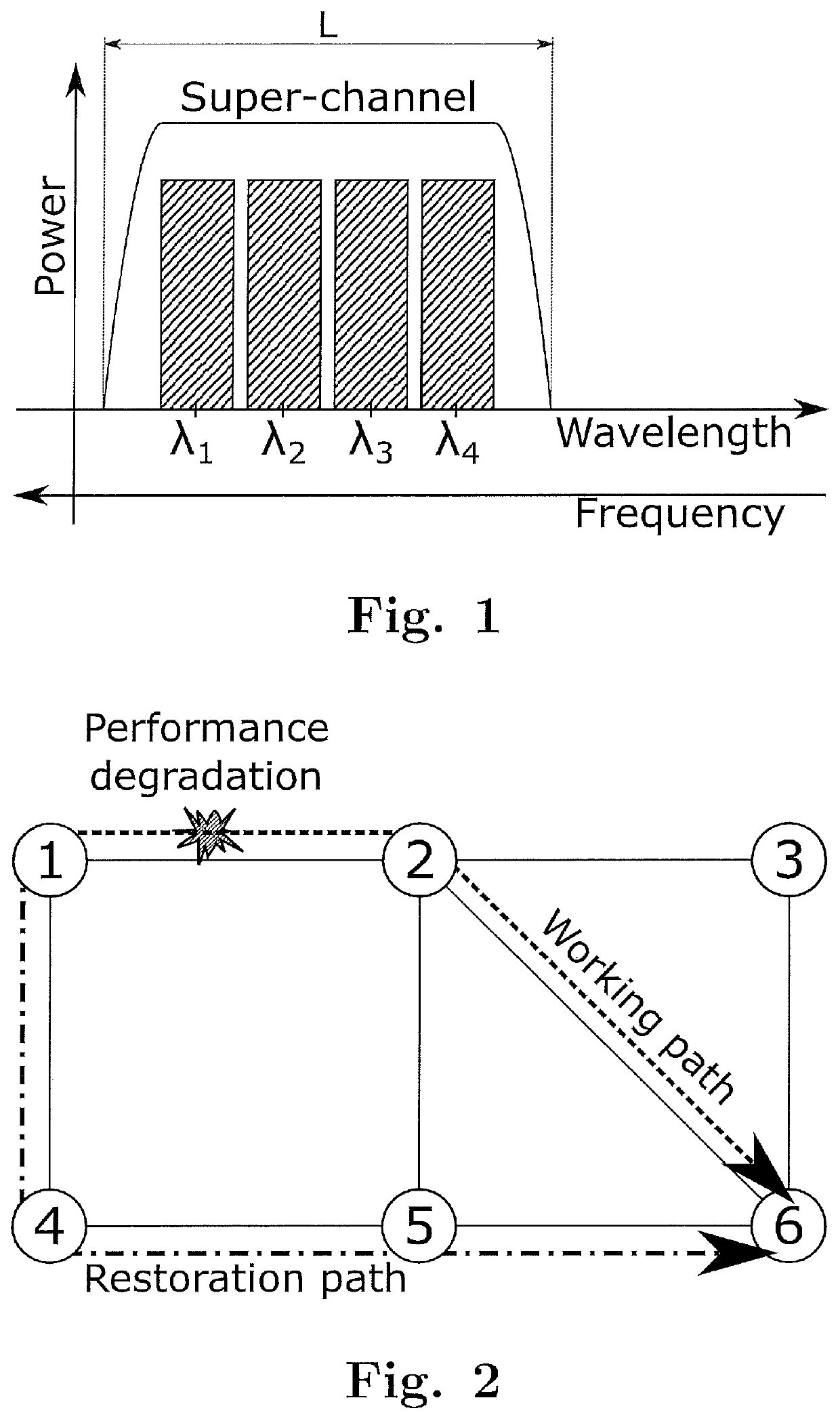
[0068]FIG. 2 schematically shows an optical network comprising six nodes 1 to 6 connected by optical links. According to an embodiment of the method of the invention, a data stream is transmitted from a first location at node 1 to a second location at node 6 along a working path via node 2, wherein the data stream is transmitted in the form of a super channel like that shown in FI...


PUM


Abstract

Disclosed herein is a method of transmitting a data stream from a first location to a second location through an optical network, as well as a corresponding performance monitoring unit, a transmitting arrangement and a receiving arrangement. The method comprises the steps of transmitting said data stream from said first location to said second location along a working path, wherein said data stream is transmitted in the form of a super channel comprising a number of n wavelengths within a predefined reserved wavelength range, monitoring the performance of the transmission based on the super channel signal received at said second location, and in case the performance is observed to drop below a predetermined performance threshold, unburdening the super channel from a part of said data stream while maintaining the reserved wavelength range for said super channel, by redirecting said part of the data stream for transmittal along at least one restoration path connecting said first and second locations, and transmitting the remainder of said data stream within the super channel on a number of wavelengths that is less than n, and/or with a reduced transmission rate for at least some of the wavelengths in said super channel.

Description

FIELD OF THE INVENTION[0001]The present invention is in the field of optical communication systems. In particular, the present invention relates to a method of transmitting a datastream through an optical network using super channels, as well as a related performance monitoring unit, transmitting arrangement, and receiving arrangement.BACKGROUND OF THE INVENTION[0002]The transmission of data in optical networks is inevitably exposed to failures that might affect the correct transmission of the data between nodes of the optical network. Such failures may for example be due to transmission fiber impairment, for example due to fiber aging or degradation, nonlinear fiber effects, optical equipment impairment, such as filter drift, optical component aging or outage due to polarization related effects. Further sources of failure can be due to the influence of external factors, such as weather conditions, seismic movements and the like, fiber repair or other kind of maintenance work in the...

Claims


Application Information

Patent Timeline
Patent Type & Authority Applications(United States)
IPC IPC(8): H04J14/02
CPCH04J14/0298H04J14/0287
Inventor RAFIQUE, DANISHRAPP, LUTZ
Owner XIEON NETWORKS SARL
Why Eureka
Try Eureka