Assembly and container for physical vapor deposition with heat dissipation

Inactive Publication Date: 2020-08-06
ESSILOR INT CIE GEN DOPTIQUE
View PDF0 Cites 0 Cited by
  • Summary
  • Abstract
  • Description
  • Claims
  • Application Information

AI Technical Summary

Benefits of technology

[0013]Providing a container, or a liner, with a surface contact with the crucible cavity at a lateral upper part of the container while keeping a lateral lower part of the container distant from the cavity crucible respectively allows to minimize cooling a

Problems solved by technology

After an extended period of use, bulges are formed at the cake top surface rendering evaporation of the material difficult.
If evaporation of the material is not sufficient, optical layers applied to the lenses or other optical devices are not enough homogeneous and thus non-compliant to expected qua

Method used


Image

  • Assembly and container for physical vapor deposition with heat dissipation
  • Assembly and container for physical vapor deposition with heat dissipation

Examples


Embodiment Construction

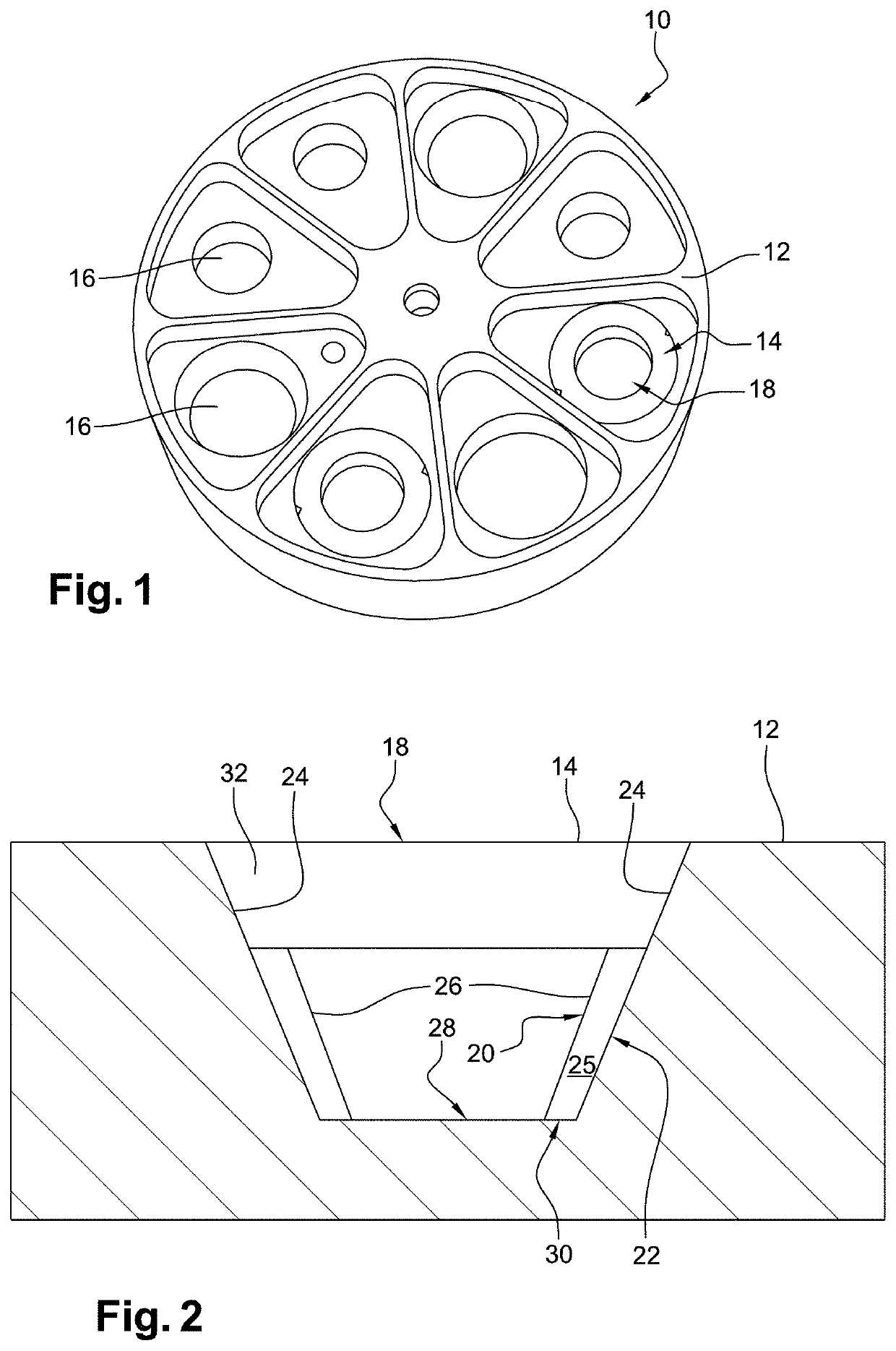
[0034]As shown on FIG. 1, an assembly 10 for Physical Vapor Deposition comprises a crucible 12 and a container 14, or liner, intended to be disposed inside a cavity 16 of the crucible 12. Said crucible 12 may have substantially the form of a disk comprising a plurality of cavities 16, also named “pockets”, suitable for receiving a container 14 in each cavity 16. More generally, the assembly 10 may have a crucible 12 with at least one cavity 16 and at least one container 14 configured to be disposed within said cavity 16. The crucible 12 is preferably made in a material having a good thermal conductivity as copper. The container 14 is preferably made in molybdenum or tungsten.

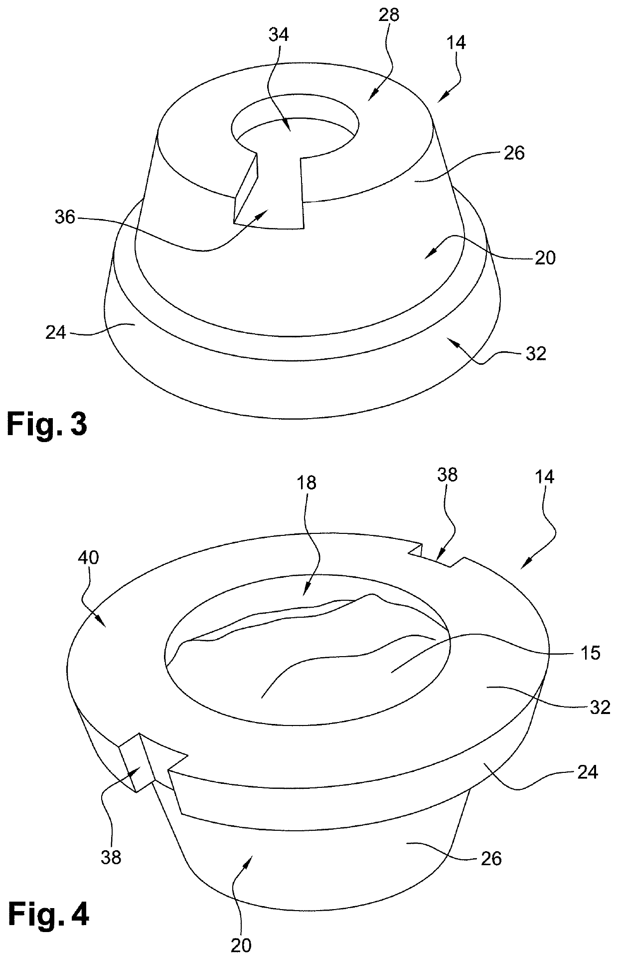
[0035]The container 14 is configured to receive a material 15 (shown on FIG. 4) to be vaporized by an electron beam gun on an ophthalmic lens. Particularly, the container 14 comprises a container cavity 18 configured to receive said material 15. When disposed in the container 14, said material 15 is bombarded wi...


PUM

PropertyMeasurementUnit
Fractionaaaaaaaaaa
Fractionaaaaaaaaaa
Fractionaaaaaaaaaa

Abstract

Disclosed is an assembly including: a crucible including at least one cavity; a container for a material to be vaporized, the container being intended to be disposed inside the cavity of the crucible. The container includes: a container lateral surface including an upper part and a lower part, the upper part being configured to be at least partially in surface contact with a cavity lateral surface when the container is disposed inside the cavity, the lower part being configured to be distant from the cavity lateral surface to form a free space surrounding the container between the lower part and the cavity lateral surface when the container is disposed inside the cavity; and a container bottom surface configured to be at least partially in contact with a cavity bottom surface.

Description

BACKGROUND OF THE INVENTIONField of the Invention[0001]The invention concerns an assembly for physical vapor deposition of a material layer on a surface. The invention further concerns a container specifically configured to be implemented in said assembly.DESCRIPTION OF THE RELATED ART[0002]Layer deposition is a process applied in many industries to form coating so as to protect surfaces and / or to impart a variety of desired properties to said surfaces. For example, in optics, an antireflective or anti-reflection (AR) layer is a type of optical layer applied to the surface of lenses or other optical devices to reduce reflection.[0003]Physical Vapor Deposition is a well-known process performed under vacuum in which a target consisting of a material is bombarded with an energy beam. The energy beam causes atoms from the target to transform into the gaseous phase. These atoms then precipitate into solid form, coating simultaneously the plurality of substrates in a vacuum chamber with a...

Claims


Application Information

Patent Timeline
IPC IPC(8): C23C14/24
CPCC23C14/243C23C14/30H01J37/3053H01J2237/002H01J2237/3132
Inventor PAGNON, PHILIPPE
Owner ESSILOR INT CIE GEN DOPTIQUE
Why Eureka
Try Eureka