Conduit system

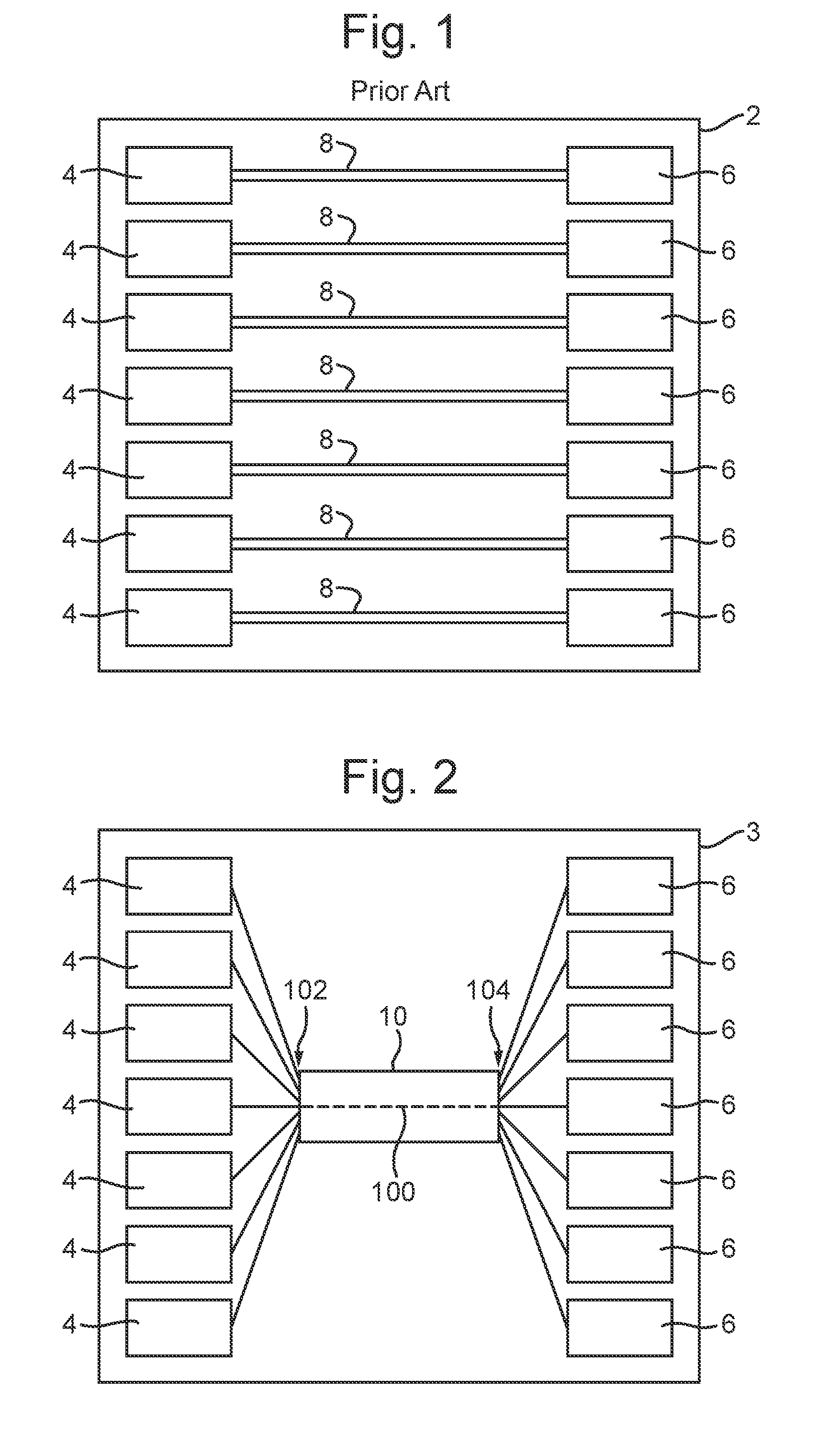
a conduit system and conduit technology, applied in the field of conduit systems, can solve the problems of time-consuming and expensive installation of conduits into first aircraft, individual conduits b>8/b>, and the installation of conduits into the first aircraft b>2/b>

Inactive Publication Date: 2016-07-14
BAE SYSTEMS PLC
View PDF18 Cites 3 Cited by
  • Summary
  • Abstract
  • Description
  • Claims
  • Application Information

AI Technical Summary

Benefits of technology

[0020]The step of arranging may further comprise minimising a thickness of the common conduit wall shared by the first and second conduits.
[0021]Arranging the conduits may comprise positioning the first and second conduits such that a distance between the first and second conduits in the nested configuration is maximised.

Problems solved by technology

The production the individual conduits 8, and the installation of said conduits into the first aircraft 2, tend to be time consuming and expensive at least in part due to the significant number of manufacturing and installation steps involved.

Method used


Image

  • Conduit system
  • Conduit system
  • Conduit system

Examples


Embodiment Construction

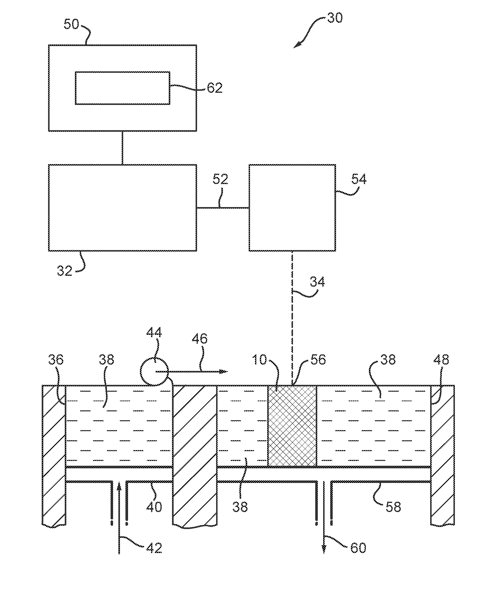
[0050]The terminology “source apparatus” is used herein to refer to a system or apparatus from which a resource, such as power, information, matter etc. is to be transferred.

[0051]The terminology “sink apparatus” is used herein to refer to a system or apparatus to which a resource, such as power, information, matter etc. is to be transferred.

[0052]The terminology “conduit” is used herein to refer to any duct, pipe, channel, pipeline, tube, canal, trough, piping, etc. that may be used to convey a resource from one location to a different location, for example, from a source apparatus to a sink apparatus. For example, a conduit may be used to transfer a fluid from one location to a different location, or may be used to house or guide a fluid (such as hydraulic fluid) or an elongate entity (such as electric wire or cable, or an optical fibre) between two different locations.

[0053]The terminology “Additive Manufacturing” is used herein to refer to all additive processes that may be used...


PUM

PropertyMeasurementUnit
poweraaaaaaaaaa
temperatureaaaaaaaaaa
temperaturesaaaaaaaaaa

Abstract

Disclosed are a method and apparatus for producing a conduit system (10) for use on-board a vehicle (3). The method comprises: identifying a plurality of source apparatuses (4) located on-board the vehicle (3) and from which a resource is to be transferred via the conduit system (10); for each identified source apparatus (4), identifying one or more sink apparatuses (6) located on-board the vehicle (3) and to which that source apparatus (4) is to transfer, via the conduit system (10), a resource; using relative locations of the identified source and sink apparatuses, producing a digital model (62) for the conduit system (10) including specifying conduits (12-24) for coupling the source apparatuses (4) to the sink apparatuses (6) and arranging the conduits (12-24) such that each conduit (12-24) shares a common conduit wall with at one other conduit (12-24); and, using the digital model (62), producing the conduit system (10).

Description

FIELD OF THE INVENTION[0001]The present invention relates to conduit systems and the manufacturing thereof.BACKGROUND[0002]Additive Manufacturing (AM) (also known as Additive Layer Manufacture (ALM), 3D printing, etc.) is a process that may be used to produce functional, complex objects, layer by layer, without moulds or dies. Typically, such processes include providing material (e.g. metal or plastic) in the form of a powder or a wire, and, using a powerful heat source such as a laser beam, electron beam or an electric, or plasma welding arc, melting an amount of that material and depositing the melted material (e.g. on a base plate of a work piece). Subsequent layers are then built up upon each preceding layer.[0003]Example AM processes include, but are not limited to, Laser Blown Powder, Laser Powder Bed, and Wire and Arc technologies.[0004]In a separate field, in many vehicles, conduits, for example pipes or tubes, are used to convey fluids, such as fuel or a coolant, from a sou...

Claims


Application Information

Patent Timeline
Patent Type & Authority Applications(United States)
IPC IPC(8): B22F5/10B64F5/00B64D37/00B22F3/105B23P15/26
CPCB22F5/106B22F3/1055B23P15/26B33Y80/00B64F5/00B33Y10/00B64D37/005F28F2255/18F28D2021/0021F28D2021/008G05B19/4099G05B2219/49007G05B2219/49008G05B2219/49018G06F2113/16G06F2113/14G06F30/15G06F2119/08Y02P10/25B22F10/18B22F10/28B22F10/25B22F10/36B22F10/12B22F12/47B22F10/14G06F30/00
Inventor MARK, POTTER ALFRED
Owner BAE SYSTEMS PLC
Why Eureka
Try Eureka