Gain-coupled resonator gyroscope

a gyroscope and resonator technology, applied in the field of optical gyroscopes, can solve the problems of erroneous claims, insufficient fiber length reduction, and insufficient concomitant size, weight and material costs,

Active Publication Date: 2020-08-06
THE BOARD OF TRUSTEES OF THE LELAND STANFORD JUNIOR UNIV
View PDF0 Cites 6 Cited by
  • Summary
  • Abstract
  • Description
  • Claims
  • Application Information

AI Technical Summary

Benefits of technology

[0007]In certain embodiments, a method of operating a gyroscope comprises providing a gyroscope comprising at least one optical waveguide comprising a first portion, a second portion, and a third portion, the second portion between the first portion and the third portion. The gyroscope further comprises at least one light source in optical communication with the first portion of the at least one optical waveguide. The gyroscope further comprises a first optical resonator in optical communication with the second portion of the at least one optical waveguide. The first optical resonator has an input coupling rate Kin with the second portion of the at least one optical waveguide. The gyroscope further comprises a second optical resonator in optical communication with the first optical resonator with an inter-resonator coupling

Problems solved by technology

The concomitant size, weight, and material costs disqualify FOGs for many large-volume applications where these parameters, especially compactness, are critical.
Resonant fiber optic gyroscopes (RFOGs) therefore utilize much shorter fibers, and can be

Method used


Image

  • Gain-coupled resonator gyroscope
  • Gain-coupled resonator gyroscope
  • Gain-coupled resonator gyroscope

Examples


Embodiment Construction

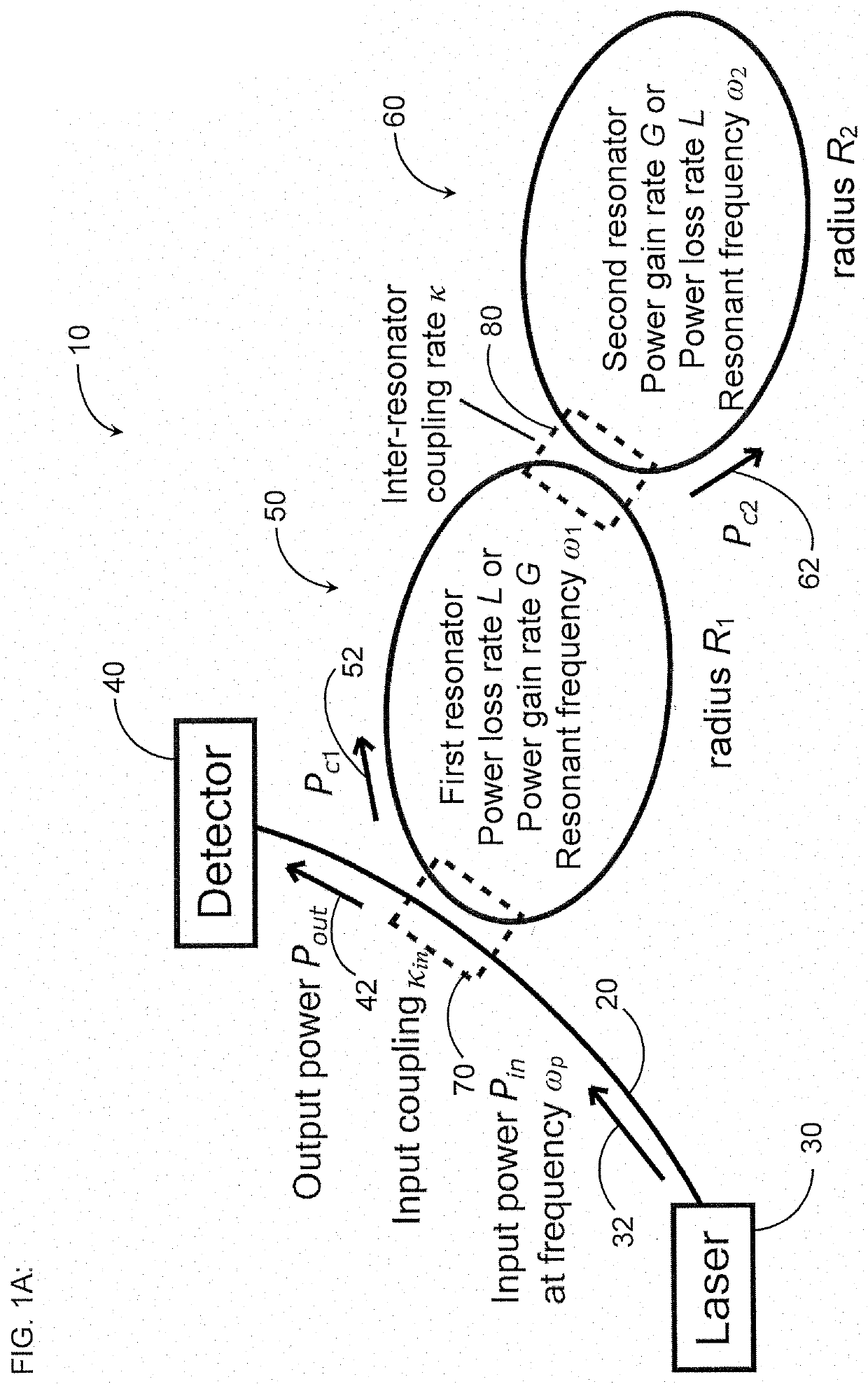
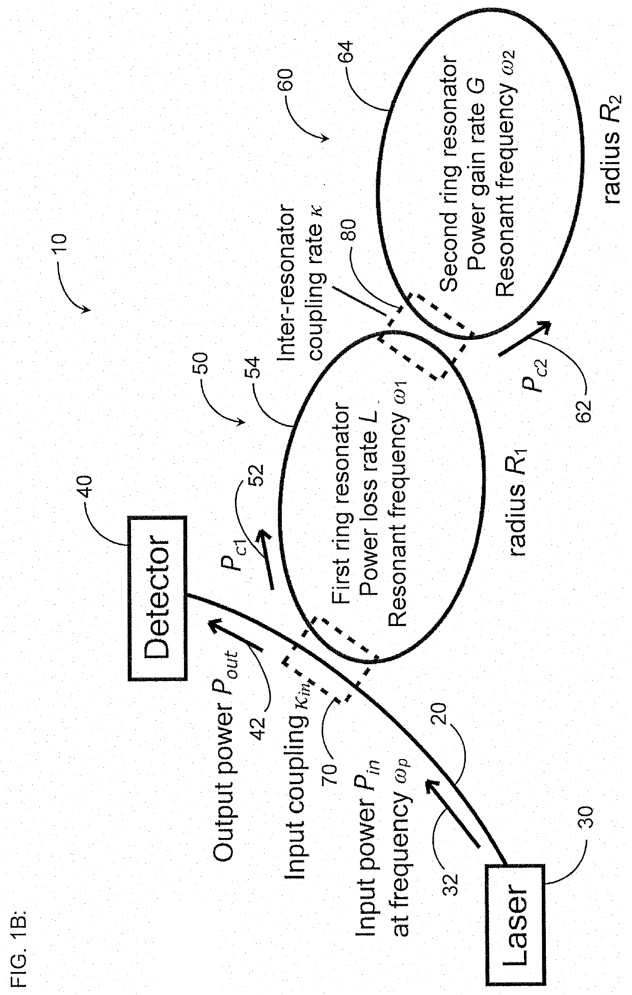
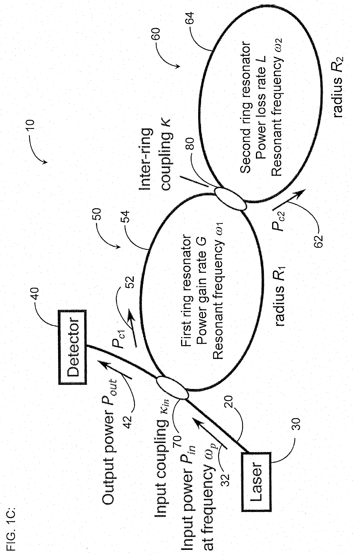
[0030]Coupled optical resonators with parity-time (PT) symmetry exhibit exceptional points where they become extremely sensitive to external perturbations (see, e.g., Ren et al., “Ultrasensitive micro-scale parity-time-symmetric ring laser gyroscope,” Opt. Lett. Vol. 42, No. 8, pp. 1556-1559 (Apr. 15, 2017)(“Ren”)) and so have gained interest in research as sensors, in particular as highly sensitive gyroscopes. In one particular physical embodiment, PT symmetry is achieved by coupling together two ring resonators, each with identical resonance frequencies, and pumping one ring such that it exhibits a gain equal to the loss of the other ring [see, e.g., B. Peng et al., “Parity-time-symmetric whispering-gallery microcavities,”Nat. Phys., vol. 10, no. 5, pp. 394-398, 2014 (“Peng”)].

[0031]Previous work has proposed that such an optical gyroscope operated at an exceptional point (EP) is responsive to rotations of magnitude Ω by shifting the resonant frequencies of the optical gyroscope i...


PUM


Abstract

A gyroscope includes a first optical resonator in optical communication with at least one optical waveguide and a second optical resonator in optical communication with the first optical resonator. One of the first optical resonator and the second optical resonator has a power loss rate L greater than zero and the other of the first optical resonator and the second optical resonator has a power gain rate G greater than zero. The at least one optical waveguide, the first optical resonator, and the second optical resonator are configured to be below lasing threshold. The gyroscope further includes at least one optical detector in optical communication with the at least one optical waveguide, and the at least one optical waveguide is configured to receive, from at least one light source, light having an input power Pin at a frequency ωp and to transmit at least a portion of the light having an output power Pout to the at least one optical detector.

Description

CLAIM OF PRIORITY[0001]This application claims the benefit of priority to U.S. Provisional Appl. No. 62 / 800,149, filed Feb. 1, 2019 and incorporated in its entirety by reference herein.BACKGROUNDField[0002]This application relates generally to optical gyroscopes.Description of the Related Art[0003]High-accuracy optical gyroscopes rely on the Sagnac effect, which produces a phase shift in the light traveling along a length of fiber that is rotated. The Sagnac phase accumulated in one round-trip through a loop of fiber is proportional to the area subtended by the loop. For the small rotation rates of interest for inertial navigation of aircraft (e.g., less than 0.01° / h), the Sagnac phase shift is very small. Fiber optic gyroscopes (FOGs) have therefore used fiber coils with a very large area subtended by a long fiber (e.g., typically 100-1000 meters and wound in multiple turns). The concomitant size, weight, and material costs disqualify FOGs for many large-volume applications where t...

Claims


Application Information

Patent Timeline
IPC IPC(8): G01C19/72
CPCG01C19/723G01C19/722G01C19/64G01C19/72
Inventor DIGONNET, MICHEL J.F.GRANT, MATTHEW JAMES
Owner THE BOARD OF TRUSTEES OF THE LELAND STANFORD JUNIOR UNIV
Why Eureka
Try Eureka