Binary Passive Variable Stiffness Joint

a passive variable and joint technology, applied in the field of stiffness joints, can solve the problems of high energy consumption, complex control system, and need of accurate and expensive force or torque sensors, and achieve the effect of altering the stiffness levels of robotic joints

Active Publication Date: 2020-08-13
KHALIFA UNIV OF SCI & TECH
View PDF0 Cites 7 Cited by
  • Summary
  • Abstract
  • Description
  • Claims
  • Application Information

AI Technical Summary

Benefits of technology

[0008]Therefore it is an object of the present invention to provide a system and method for altering

Problems solved by technology

The disadvantages of this system include high energy consumption, the need of accurate and expensive force or torque sensors, complexity of the control system, incapability of storing energy and absorbing shocks.
Drawbacks involved with the SEA included non-optimal performance energy efficiency.
Although different variable stiffness joint

Method used


Image

  • Binary Passive Variable Stiffness Joint
  • Binary Passive Variable Stiffness Joint
  • Binary Passive Variable Stiffness Joint

Examples


Embodiment Construction

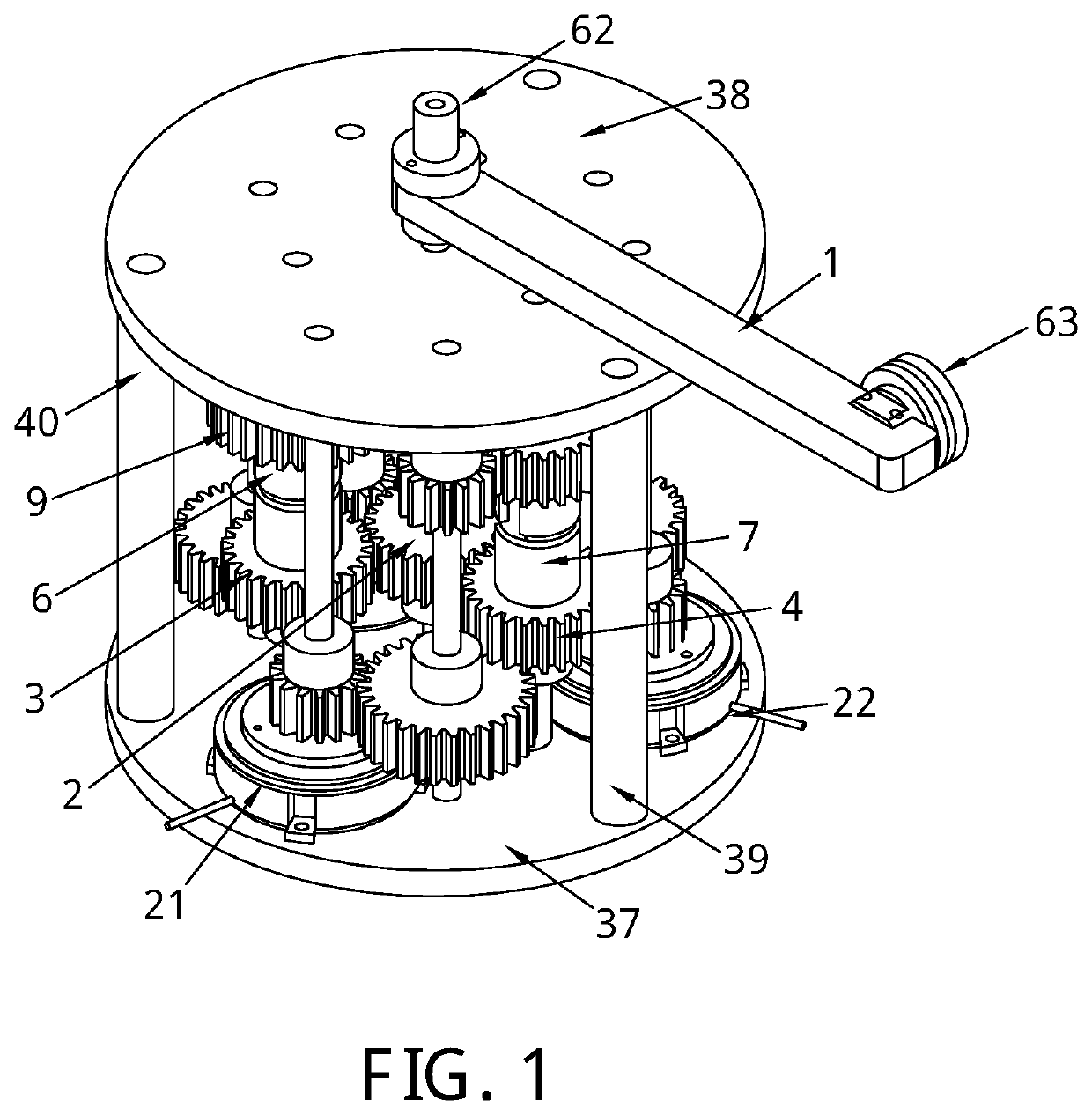
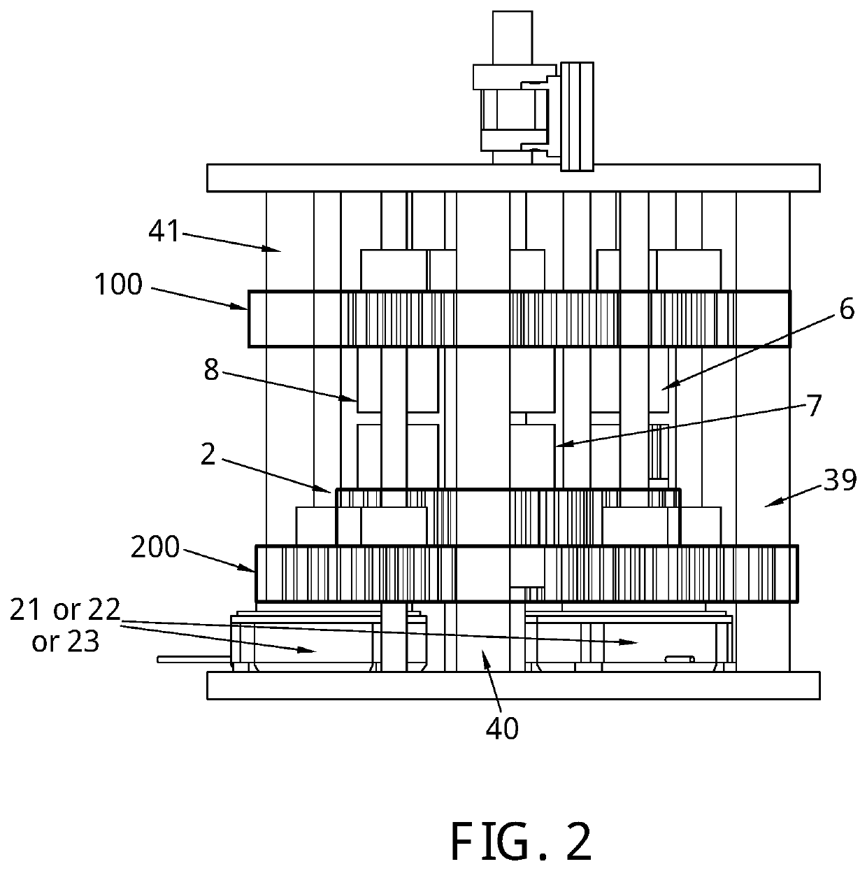
[0049]The invention introduces a system and mechanism to alter the stiffness of a robotic revolute joint according to a number of stiffness levels, by proposing the design of a passive binary controlled variable stiffness joint (BpVSJ).

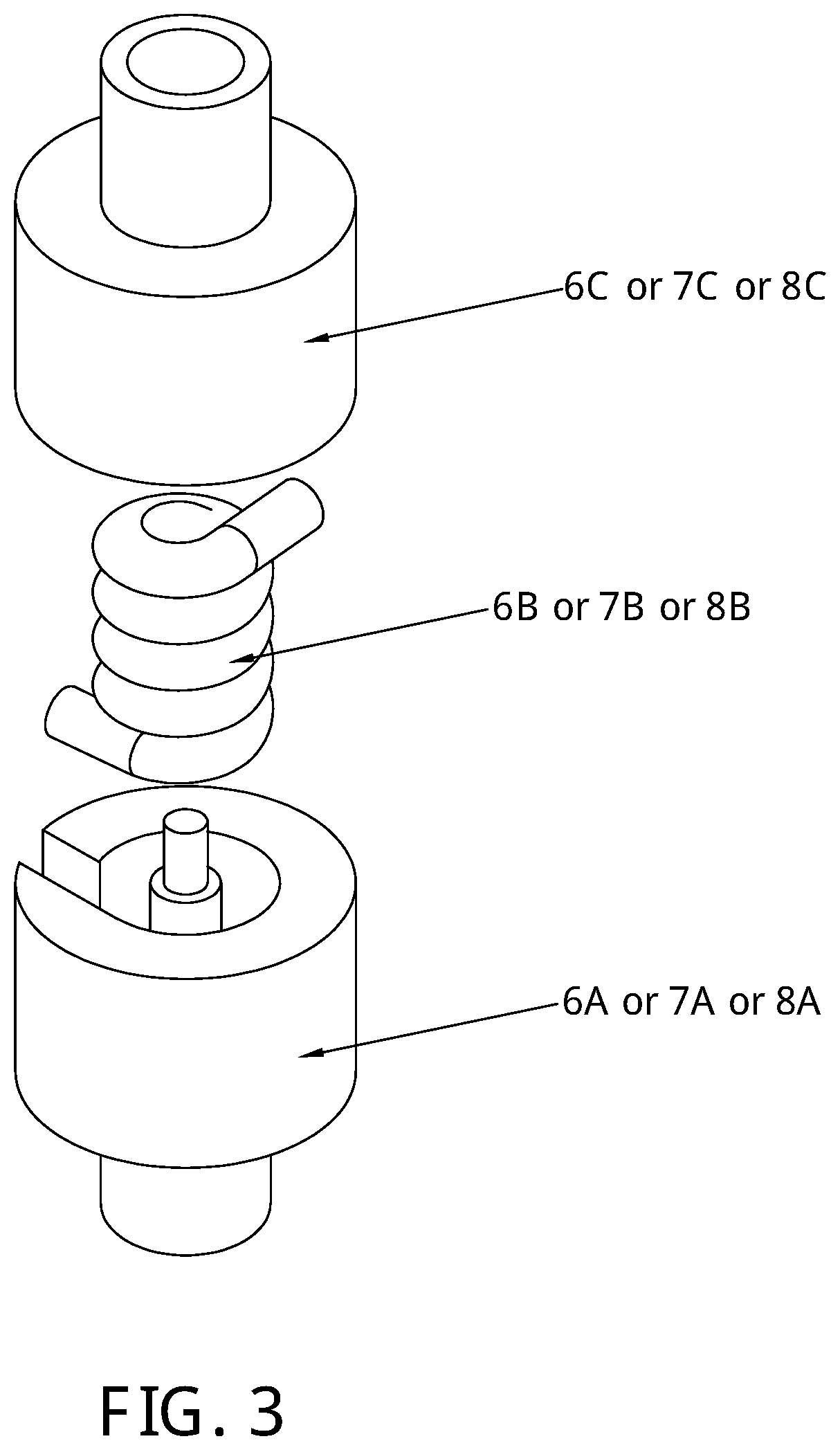
[0050]In a preferred embodiment of the invention, as shown in FIG. 1-6, the structure of the variable stiffness joint comprises of two bases 37 and 38 connected using three frame rods 39, 40, and 41. An output link 1 is mounted on a shaft 24 which is mounted on bases 37 and 38. Shaft 24 holds also a main driving gear 2 which connects with three planetary gears 3, 4, and 5 in a (1:1) ratio. Each of these three gears is mounted on shafts 25, 26 and 27 respectively. These shafts are held to the lower base 37. Each of these shafts holds the lower container—6A, 7A and 8A respectively—of three elastic elements 6B, 7B and 8B respectively. The elastic elements are torsional springs. Each of these torsional springs is encapsulated in upper containers 6C, 7C an...


PUM


Abstract

A variable stiffness joint and method to alter the stiffness of the joint with multiple stiffness levels is described wherein a plurality of stiffness bits (m) are used for enabling 2 m stiffness level variations for the joint. Each stiffness bit comprises an elastic element in mechanical connection with a clutch (21, 22, 23). The joint revolves with zero stiffness level when all the clutches (21, 22, 23) are disengaged whereas a clutch (21, 22, 23) involves one of the elastic elements which alter the stiffness of the joint. Engaging other clutches (21, 22, 23) involve more elastic elements for altering the joint stiffness and the resultant joint stiffness is determined by adding the stiffness values of all the involved springs (6, 7, 8).

Description

FIELD OF THE INVENTION[0001]The present invention relates to stiffness joints and more specifically, the present invention relates to a variable stiffness joint and method for altering the stiffness of a robotic joint. A stiffness of the joint is varied according to a number of stiffness levels in order to enhance safety interactions.BACKGROUND OF THE INVENTION[0002]There has been a rapid development in the fields of wearable robotics and compliant actuators during the past few decades. This has resulted in robots operating closely with humans, physically interacting or even being worn by humans which has further led to the rise of several safety aspects and design requirements. Safety should be an essential feature in robots especially in the case of unexpected interactions or sensor failures. Other than the safety aspect, applications such as rehabilitation robots, exoskeletons and haptics have proved that the interaction between the robot and the operator must show adaptability a...

Claims


Application Information

Patent Timeline
IPC IPC(8): B25J19/06B25J17/02
CPCB25J17/0266B25J9/126B25J9/102B25J17/0208B25J19/068F16D3/50A61B34/30F16H57/08F16D3/10F16D3/66F16D3/56F16D3/64
Inventor AWAD, MOHAMMADGAN, DONGMINGDIAS, JORGESENEVIRATNE, LAKMAL
Owner KHALIFA UNIV OF SCI & TECH
Why Eureka
Try Eureka