Model predictive control of torque converter clutch slip

a technology of torque converter and clutch, applied in the direction of gearing control, gearing elements, gearing, etc., can solve the problems of inability to lock tcc, inability to control and inability to detect the slip of the clutch

Active Publication Date: 2020-08-13
GM GLOBAL TECH OPERATIONS LLC
View PDF15 Cites 0 Cited by
  • Summary
  • Abstract
  • Description
  • Claims
  • Application Information

AI Technical Summary

Benefits of technology

[0023]According to several aspects, a system includes a torque converter that includes a torque converter clutch, a torque generative device that provides torque to the torque converter, and an actuator that controls clutch pressure of the torque converter clutch. The system also includes a controller having a clutch plant model that predicts a value of a parameter that relates to torque converter clutch slip as a function of clutch plant model inputs comprising commanded clutch pressure and of torque from the torque generative device. The system further includes a model predictive con

Problems solved by technology

Because a torque converter uses fluid coupling between its input and its output, there are inherent inefficiencies due to losses in th

Method used


Image

  • Model predictive control of torque converter clutch slip
  • Model predictive control of torque converter clutch slip
  • Model predictive control of torque converter clutch slip

Examples


second embodiment

[0052]In an aspect of this second embodiment, a clutch plant model relates the clutch torque Tc to engine torque Te and to a commanded torque actuation pressure PTcc. In the following discussion, to simplify the notation by reducing the number of subscript levels the variable name CltTrq is used to represent the clutch torque Tc.

[0053]For this second exemplary embodiment, the input and output terms in the discrete state space model may be represented as:

u=[PTcc]

y=CltTrq

Where PTcc represents TCC clutch activation pressure and CltTrq represents TCC clutch torque.

[0054]For this second exemplary embodiment, an exemplary cost function may include clutch torque error, TCC input pressure rate of change, and TCC input reference pressure error integrals. The cost function may be expressed as:

min∑k=0N-1WCltTrq(CltTrqk+1-CltTrqref,k+1)2+WΔPtcc(ΔPtcc,k)2+WPtccRef(Ptcc,k-Ptcc-ref,k)2

where:

ΔPtcc,kPtcc,k−Ptcc,k−1

subject to the constraints:

Ptcc,min,k≤Ptcc,k≤Ptcc,max,k k=0, 1, . . . , N−1

CltTrqmin,...

third embodiment

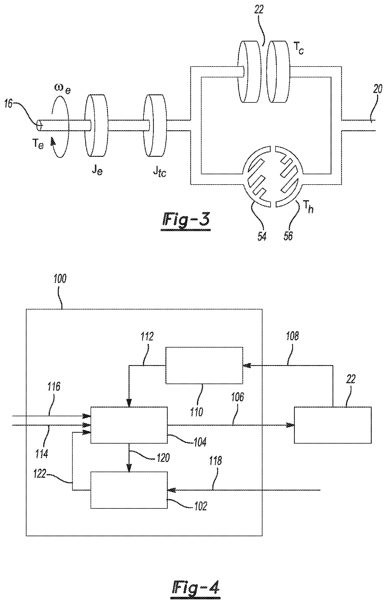
[0055]In a third exemplary embodiment, again with reference to FIG. 4, the plant model 102 is a nonlinear model of a TCC described by a linear system with nonlinear disturbances including engine torque, nonlinear part of hydraulic torque, and shaft torsional vibrations. In an aspect of this third embodiment, hydraulic torque in the operating range of interest is approximated by a second order polynomial of slip; i.e. Th≈a(slip)+b(slip)2. In this embodiment, the proposed control signal 120 is a proposed pressure command to the TCC model 102, and the predicted plant response 122 is a predicted slip level. The additional plant model inputs 118 include a reported engine torque signal, such as reported by an engine control module (ECM). The additional plant model inputs 118 also include a hydraulic torque signal. The desired operating point 114 represents a desired TCC slip level. The additional controller input signal 116 represents engine torque. The commanded control output signal 106...


PUM


Abstract

A control system to control slip of a torque converter clutch includes a clutch plant model configured to predict a value of a parameter that relates to torque converter clutch slip as a function of clutch plant model inputs comprising commanded clutch pressure and of torque from the torque generative device. The control system also includes a model predictive controller configured to receive signals that allow determination of a desired value of the parameter that relates to torque converter clutch slip and a predicted value of the parameter that relates to torque converter clutch slip, receive a signal representing reported torque of the torque generative device, identify an optimal commanded clutch pressure value that will result in an optimal value of an objective function based on the clutch plant model, and provide a command signal to an actuator effective to control commanded clutch pressure to the torque converter clutch.

Description

INTRODUCTION[0001]The present disclosure relates to control of slip in a torque converter clutch (TCC), and more specifically to control of TCC slip using model predictive control (MPC).[0002]Torque converters are commonly used to transfer drive torque from a torque generative device to a transmission. A torque converter can provide torque multiplication, smooth ratio changing on acceleration, and good torsional vibration damping. Because a torque converter uses fluid coupling between its input and its output, there are inherent inefficiencies due to losses in the fluid. To realize better fuel economy, auto makers use a locking clutch, known as a torque converter clutch or TCC, to mechanically lock the input to the output to reduce losses at steady state speed conditions. In lower gears and at low vehicle speeds, the TCC cannot be locked because a locked drivetrain would pose drivability concerns. In order to strike a balance between vehicle drivability and fuel economy, systems hav...

Claims


Application Information

Patent Timeline
IPC IPC(8): F16H61/14
CPCF16H2061/145F16H61/143F16H59/14B60W10/02B60W10/023B60W40/00F16H59/24F16H59/40
Inventor ZAVALA JURADO, JOSE C.CIMINI, GIONATAJAGIELO, BRYAN P.ZHANG, ZHENWANG, YUE-YUNATMARAM, HARINATH
Owner GM GLOBAL TECH OPERATIONS LLC
Why Eureka
Try Eureka