

Motion stabilized laser speckle imaging
a motion stabilized, laser speckle technology, applied in the field of medical devices, can solve the problems of difficult maneuverability in a crowded hospital setting, limited use of lsi in the clinic, and difficulty in generating meaningful data for handheld lsi devices
- Summary
- Abstract
- Description
- Claims
- Application Information
AI Technical Summary
Benefits of technology
Problems solved by technology
Method used
Image

Examples
example 1
Motion Stabilized Laser Speckle Imaging Device
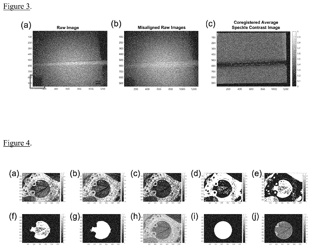
[0043]The LSI device consisted of an 8-bit, 1.32 megapixel CCD camera (CMLN-13S2M-CS, FLIR Integrated Imaging Solutions, Inc., Richmond, BC, Canada, pixel size=3.75□m), a variable zoom C-mount lens (Computar C-Mount 13-130 mm Varifocal Lens, Computar, Cary, N.C.), and 809 nm near-infrared laser diode (140 mW, Ondax Inc., Monrovia, Calif.). The laser was attached to the camera and lens setup with a custom 3D printed camera mount. The imaging system acquired 1280×960 pixel frames at 15 Hz, which resulted in a field of view (FOV) of approximately 140 mm×105 mm (4.3 ratio). The imaging system was attached to a handheld gimbal stabilizer (Crane v2 3-Axis Handheld Gimbal Stabilizer. Zhiyun-Tech) to create the motion stabilized laser speckle imaging (MSLSI) device (FIG. 1). The MSLSI device was connected to a tablet computer (Surface Pro 2, Microsoft Inc.) via a six-foot-long A-Male to Mini-B USB cable. Data were collected using the FlyCap2 Sof...
example 2
Fiducial Marker Identification
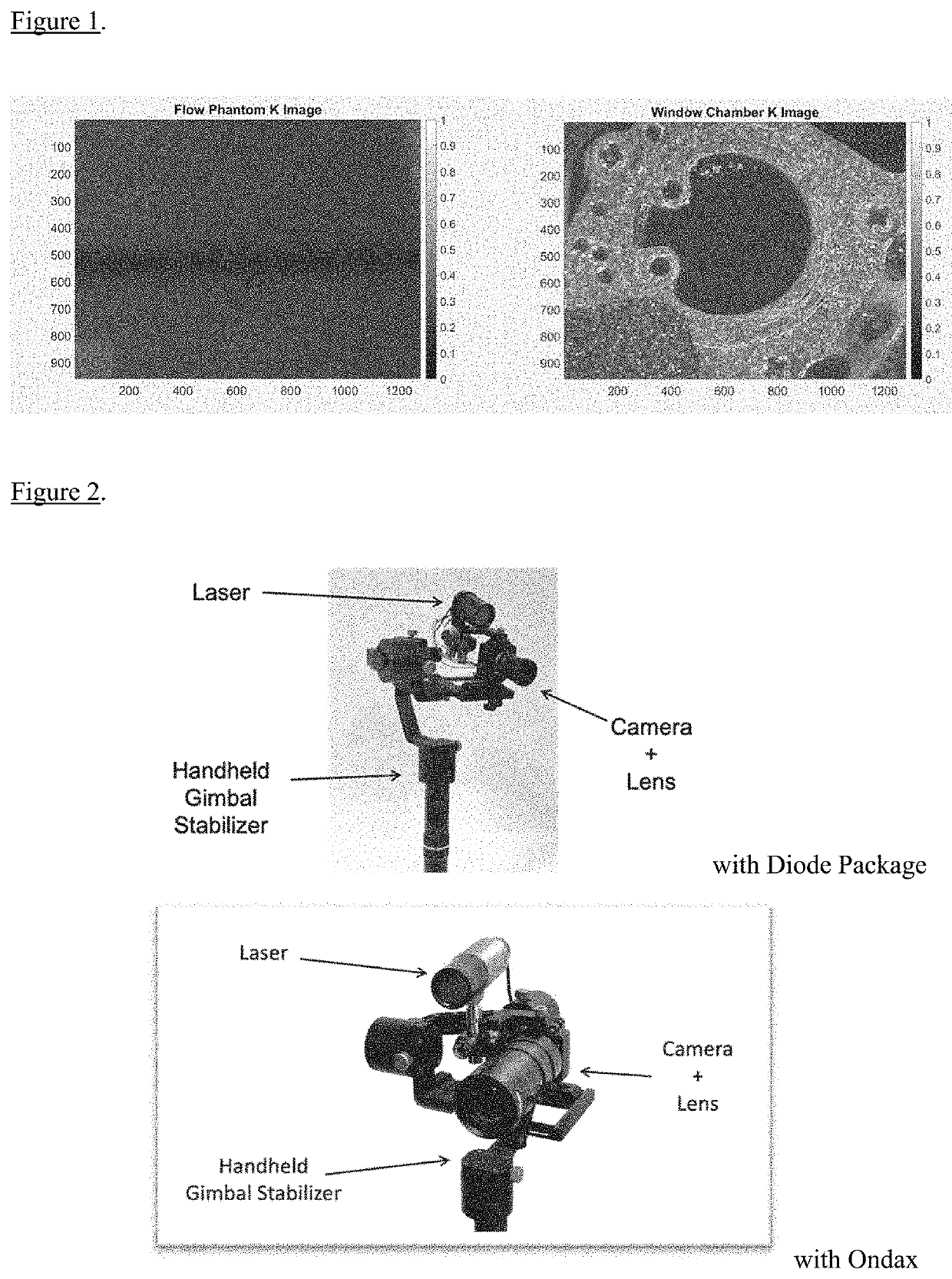
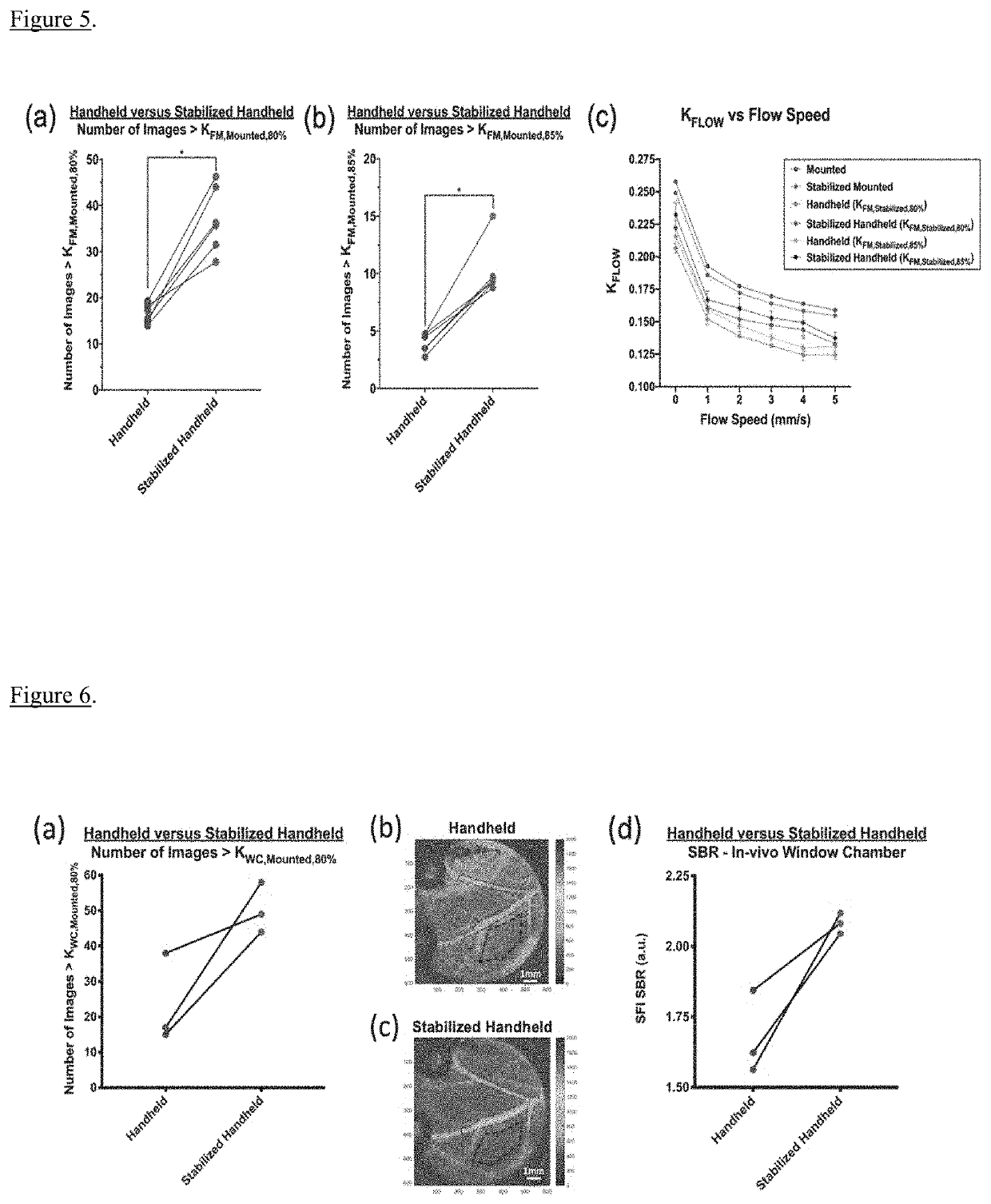
[0044]To test motion artifact reduction, the imaging system was used in a handheld manner both with and without the HGS. The setup for each configuration was comparable in weight to control for potential advantages if one load was lighter. The inventors ensured Nyquist was satisfied at all magnifications with the LSI device. A spatial processing algorithm was used to convert all raw images to speckle contrast images. The spatial processing algorithm utilized a 7×7 pixel sliding window with the relationship K=σ / calculated for each sliding window position. K is the contrast, a the standard deviation of the pixel intensities within the window, and the mean intensity of the pixels within the window. As previously described in Lertsakdadet et al., a FM made from an 18% grey card, (Neewer, model #10079934) commonly used to correct for white balance in photography, was incorporated into the imaging protocol. They utilized this FM for thresholding and image c...
example 3
In Vitro Flow Phantom Experiment
[0045]To test the hypothesis that msLSI performs better than standard handheld LSI, the inventors performed an in vitro flow phantom experiment using the LSI device in four configurations: 1) mounted, 2) mounted with gimbal stabilizer (stabilized mounted), 3) handheld, and 4) handheld with gimbal stabilizer (stabilized handheld). The FOV of the device was set to ˜140 mm×105 mm (4:3 ratio) and the exposure time of the device set to 10 ms. They used a solid silicone phantom with a surface-level inclusion flow tube (diameter 10 mm). The flow medium was a 1% Intralipid solution (Fresenius Kabi, Lake Zurich, Ill.) that was infused into the tube using a mechanical pump (NE-1000 Single Syringe Pump, Pump Systems Inc.). The flow speed of the flow medium was changed from 0 mm / s to 5 mm / s in 1 mm's increments. Sequences of 150 images were acquired with all configurations.
[0046]They wanted to compare the differences in stability due to the hardware change of acq...
PUM
 Abstract
Description
Claims
Application Information