Machine tool

Active Publication Date: 2020-08-20
MAKINO MILLING MASCH CO LTD
View PDF0 Cites 5 Cited by
  • Summary
  • Abstract
  • Description
  • Claims
  • Application Information

AI Technical Summary

Benefits of technology

[0017]According to the present invention, a machine tool that suppresses the entry of cutting flu

Problems solved by technology

As a result, the device disposed in the tool storage chamber is contaminated or broken.
However, since it is necessary to

Method used


Image

  • Machine tool
  • Machine tool
  • Machine tool

Examples


Embodiment Construction

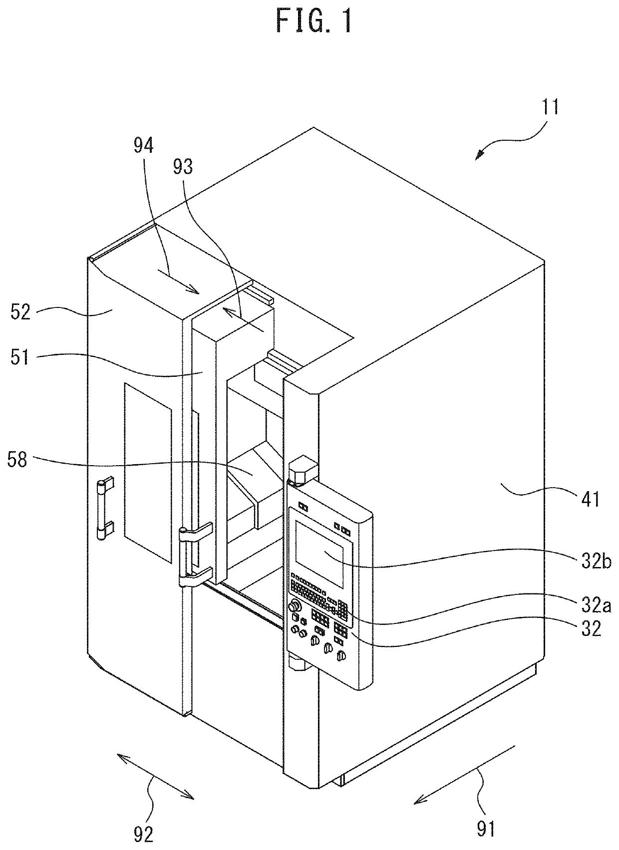
[0027]Referring to FIGS. 1 to 9, a machine tool according to an embodiment will be described below. In the present embodiment, a numerically controlled machine tool will be described as an example. The machine tool of the present embodiment includes a tool exchange device for changing a tool. The machine tool includes a machining chamber for machining a workpiece and a tool storage chamber for storing the tool.

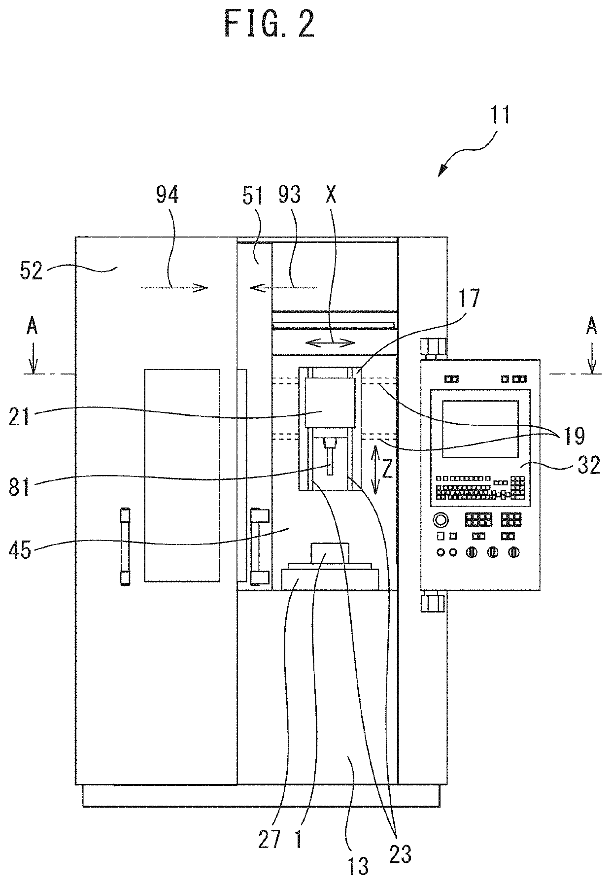
[0028]FIG. 1 is a perspective view of the machine tool according to the present embodiment. FIG. 2 is a front view of the machine tool according to the present embodiment. Referring to FIG. 1 and FIG. 2, in the present embodiment, the side of a machine tool 11 on which an operator stands will be referred to as the front side of the machine tool 11. The direction indicated by arrow 91 corresponds to the front side of the machine tool 11. FIG. 2 illustrates the machine tool 11 viewed from the front side. Moreover, the left and right direction of the machine tool 11 is referred t...


PUM


Abstract

This machine tool is provided with: a partition that partitions a machining chamber and a tool storage chamber and that has an opening; a shutter; and a receiving member that is formed so as to receive cutting fluid. The partition includes a sidewall member that extends in the vertical direction and an inclined wall member inclined in such a manner so as to become lower from the sidewall member to the interior of the machining chamber. At least part of the opening is formed in the inclined wall member. The receiving member is positioned beneath the shutter, and in such a position so as to receive cutting fluid that drops down along the sidewall member when the shutter is opened.

Description

CROSS-REFERENCE TO RELATED APPLICATIONS[0001]This application is a U.S. national phase patent application of International Patent Application No. PCT / JP2016 / 076686, filed Sep. 9, 2016, which is hereby incorporated by reference in the present disclosure in its entirety.FIELD OF THE INVENTION[0002]The present invention relates to a machine tool.BACKGROUND OF THE INVENTION[0003]In a machining chamber in which a workpiece is machined, a table for fixing a workpiece and a spindle head for holding a tool are disposed. Since chips and cutting fluid for cooling the tool are scattered in the machining chamber, a partition wall is formed so as to surround the machining chamber. Furthermore, the machine tool that includes a tool exchange device for changing a tool attached to the spindle head is known. In the machine tool including the tool exchange device, a tool storage chamber where a device for storing tools is disposed is formed. Also in the machine tool including the tool exchange device...

Claims


Application Information

Patent Timeline
IPC IPC(8): B23Q3/155
CPCB23Q3/15526Y10T483/115Y10T483/15B23Q11/0825B23Q11/08B23Q11/10B23Q11/0891B23Q3/15539B23Q3/15706B23Q3/15722B23Q11/0053B23Q11/0042Y10T483/1795Y10T483/1882B23Q3/15766
Inventor TAKADA, DAISUKETANGE, KEISUKENAKAYASU, KAZUMASA
Owner MAKINO MILLING MASCH CO LTD
Why Eureka
Try Eureka