Drivetrain layout with cvt

a technology of drivingtrain and drivetrain, which is applied in the direction of couplings, slip couplings, gearing, etc., can solve the problems of high magnitude and unpredictable, rapid transient torque, and slip condition between belts and pulleys of cvt, and may damage the cvt and other components of the vehicl

Active Publication Date: 2020-08-20
TEAM INDS
View PDF0 Cites 5 Cited by
  • Summary
  • Abstract
  • Description
  • Claims
  • Application Information

AI Technical Summary

Benefits of technology

[0006]In one embodiment, a drivetrain layout that includes a primary gear reduction, a steel belt CVT and a range box is provided. The primary gear reduction is operationally engaged to an output of a motor. The steel belt CVT includes a primary pulley and a secondary pulley. The primary pulley of the steel belt CVT is operationally engaged to the primary gear reduction. The primary gear reduction reduces a rotational speed of the output of the motor that is coupled to the primary pulley of the steel belt CVT. The range box is operationally engaged with the secondary pulley of the steel belt CVT. The range box is configured to couple torque between the steel belt CVT and wheels of a vehicle.
[0007]In another embodiment, a drivetrain layout including a primary gear reduction, a CVT, a launch clutch, a range box and a peak torque limiting (PTL) device is provided. The primary gear reduction is operationally engaged to an output of a motor. The CVT includes a primary pulley, a secondary pulley and a belt that is operationally engaged between the primary pulley and the secondary pulley. The primary pulley of the CVT is further operationally engaged to the primary gear reduction. The primary gear reduction reduces a rotational speed of the output of the motor that is coupled to the primary pulley of the CVT. The launch clutch is in operational engagement between the primary gear reduction and the primary pulley of the CVT. The range box is operationally engaged with the secondary pulley of the CVT. The range box is configured to couple torque between the CVT and wheels of a vehicle. The PTL device is in operational engagement between the secondary pulley of the CVT and the range box. The PTL device is configured to protect the drivetrain layout from transients.
[0009]In further yet another embodiment, a drivetrain layout that includes a CVT, a range box, and a PTL is provided. The CVT includes a primary pulley and a secondary pulley. The primary pulley of the CVT is operationally engaged to an output of a motor. The range box is operationally engaged with the secondary pulley of the CVT. The range box is configured to couple torque between the CVT and wheels of a vehicle. The PTL device is in operational engagement between the secondary pulley of the CVT and the range box. The PTL device configured to protect the drivetrain layout from torque transients.

Problems solved by technology

Transient torque tends to be rapid, high in magnitude and unpredictable.
Vehicles that use continuously variable transmissions (CVTs) that are subject to transient torque may result in a slip condition between a belt and pulleys of the CVT if a clamp load is not high enough to manage the transient torque.
A slip may be damaging to the CVT and other components of the vehicle.
Transient torque is difficult to manage through control strategies since reaction times of control strategies are generally not fast enough to manage the transient torque.
Further, pulleys of CVTs operated at high engine velocities, as is common in side-by-side vehicle operations, may experience hydraulic clamping due to velocity induced pressure gradients in the clamping piston.
At pulley speeds greater than 10,000 RPM, the loads can become too high for an effective variator control.

Method used


Image

  • Drivetrain layout with cvt
  • Drivetrain layout with cvt
  • Drivetrain layout with cvt

Examples


example embodiments

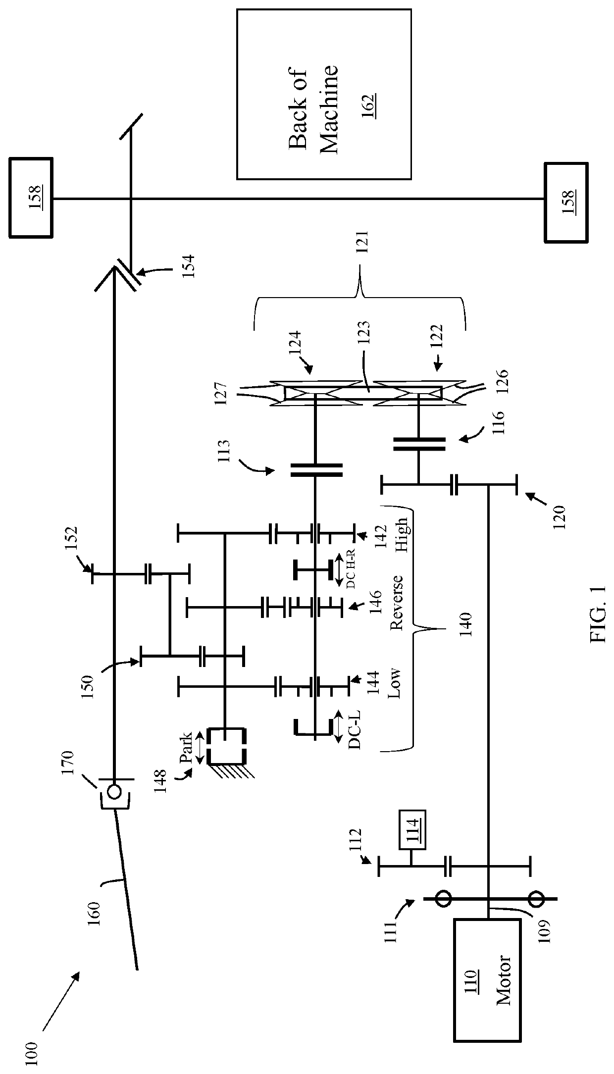
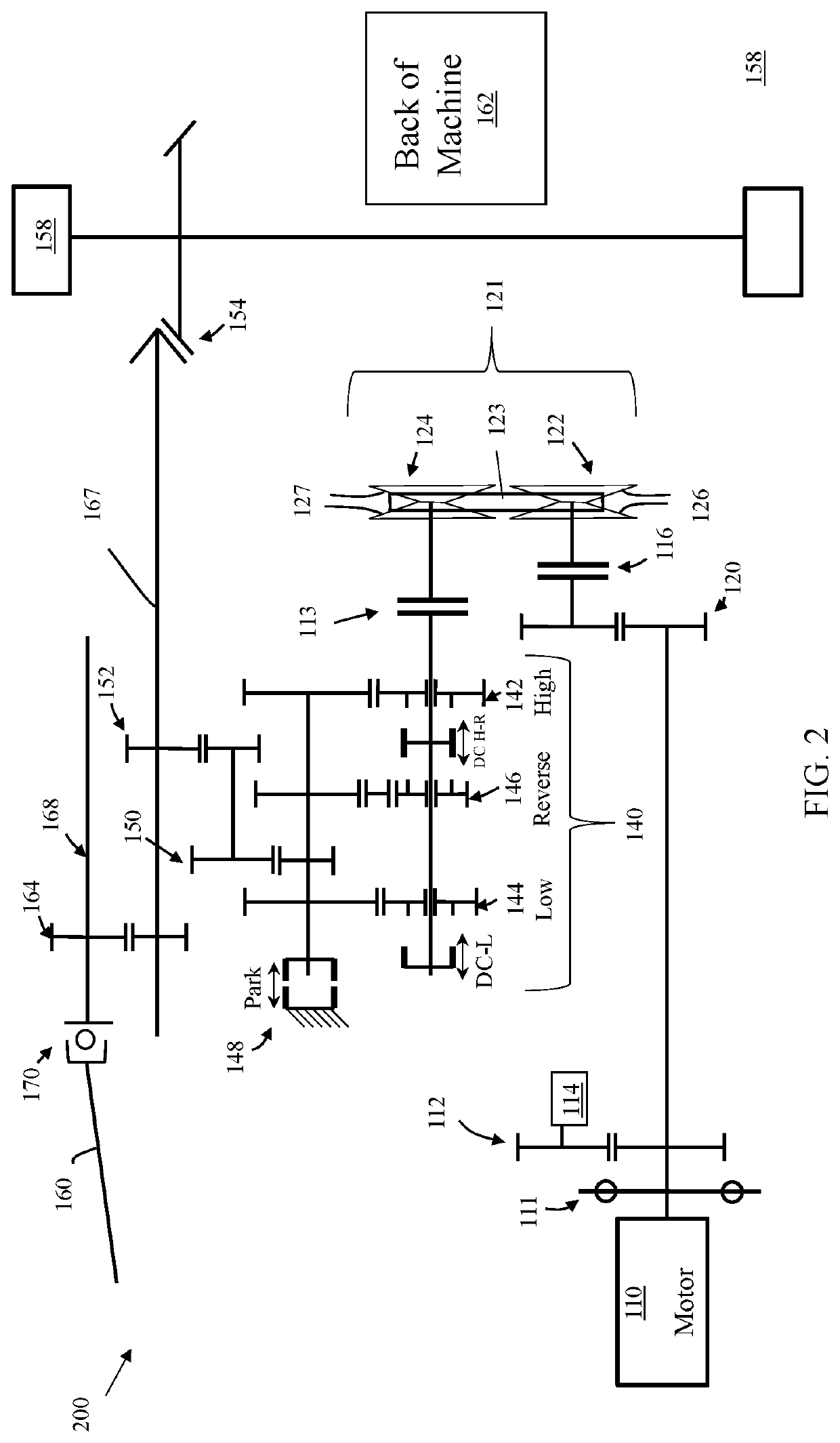
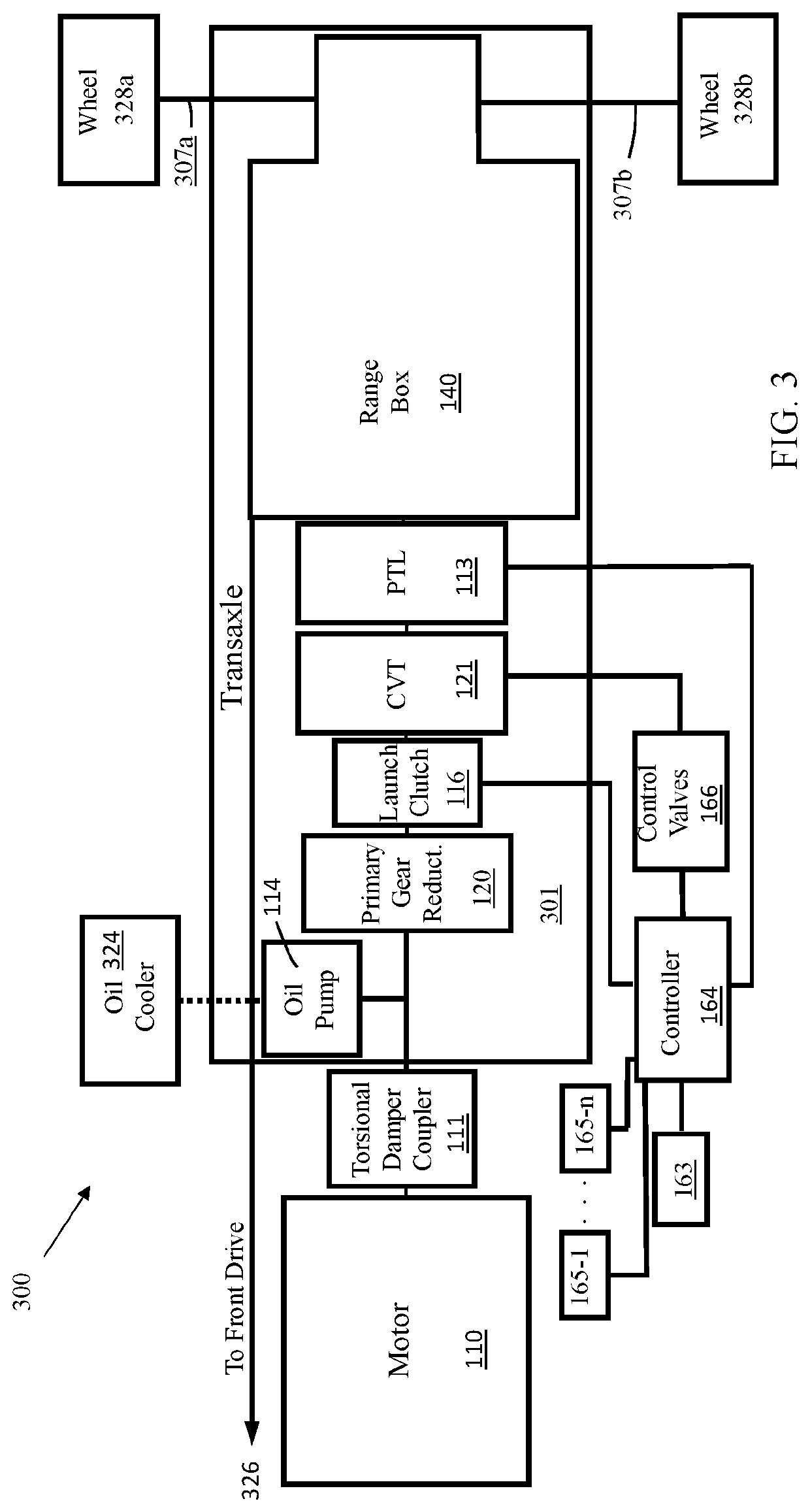
[0059]Example 1 is a drivetrain layout that includes a primary gear reduction, a steel belt CVT and a range box. The primary gear reduction is operationally engaged to an output of a motor. The steel belt CVT includes a primary pulley and a secondary pulley. The primary pulley of the steel belt CVT is operationally engaged to the primary gear reduction. The primary gear reduction reduces a rotational speed of the output of the motor that is coupled to the primary pulley of the steel belt CVT. The range box is operationally engaged with the secondary pulley of the steel belt CVT. The range box is configured to coupled torque between the steel belt CVT and wheels of a vehicle.

[0060]Example 2, includes the drivetrain layout of Example 1, further including a launch clutch that is in operational engagement between the output of the motor and the primary pulley of the steel belt CVT.

[0061]Example 3 includes the drivetrain layout of any of Example, wherein the primary gear reduction furthe...


PUM


Abstract

A drivetrain layout that includes a primary gear reduction, a continuously variable transmission (CVT), a peak torque limiting (PTL) device and a range box is provided. The primary gear reduction is operationally engaged to an output of a motor. The CVT includes a primary pulley and a secondary pulley. The primary pulley of the CVT is operationally engaged to the primary gear reduction. The primary gear reduction reduces a rotational speed of the output of the motor that is coupled to the primary pulley of the CVT. The range box is operationally engaged with the secondary pulley of the CVT. The range box is configured to coupled torque between the CVT and wheels of a vehicle. The PTL device in operational engagement between the secondary pulley of the CVT and the range box, the PTL device configured to protect the drivetrain layout from torque transients.

Description

CROSS-REFERENCE TO RELATED APPLICATIONS[0001]This application claims priority to U.S. Provisional Application Ser. No. 62 / 808,272 titled “Drivetrain Layout with Steel Belt CVT” filed on Feb. 20, 2019, which is incorporated in its entirety herein by reference.BACKGROUND[0002]Side by side vehicles are commonly operated in off-road conditions. Vehicles that are operated in off-road conditions are subject to transient torque events that are greater than those seen by on-road vehicles. Example of conditions that generate transient torque include jumps, sharp bumps and even uneven terrain. Transient torque tends to be rapid, high in magnitude and unpredictable. Vehicles that use continuously variable transmissions (CVTs) that are subject to transient torque may result in a slip condition between a belt and pulleys of the CVT if a clamp load is not high enough to manage the transient torque. A slip may be damaging to the CVT and other components of the vehicle. Transient torque is difficul...

Claims


Application Information

Patent Timeline
Patent Type & Authority Applications(United States)
IPC IPC(8): B60K17/04F16H37/02B60K17/02F16D7/00F16D3/12B60K17/28B60K25/02F16H57/04
CPCF16H37/022F16H57/0441B60K25/02F16H2702/00B60K17/28B60K17/34F16H37/021F16H2702/02F16D7/00B60K17/02B60K17/04F16D3/12B60K2025/022F16H2037/023F16H61/6649F16D7/027
Inventor YOUNGGREN, BRUCE H.DUNLAP, JOELMAKI, GREGORY LEEFISK, JORDAN E.YUDELL, ALEXANDER C.
Owner TEAM INDS
Why Eureka
Try Eureka