Device and Method for Monitoring a Sensor Clock Signal

a technology of sensor clock and device, which is applied in the direction of synchronising signal speed/phase control, generating/distributing signals, instruments, etc., can solve the problems of sensor clock oscillator drifting off or breaking, signal distortion of sensor units on the psi5 bus, etc., to achieve faster alerts, increase diagnostic coverage of corresponding airbag systems, and improve road safety

Active Publication Date: 2020-08-20
ROBERT BOSCH GMBH
View PDF0 Cites 1 Cited by
  • Summary
  • Abstract
  • Description
  • Claims
  • Application Information

AI Technical Summary

Benefits of technology

[0005]The method for monitoring a sensor clock signal in a sensor unit with the features of independent claim 1 and the device for monitoring a sensor clock signal in a sensor unit with the features of independent claim 7 have the advantage that an error of the sensor oscillator can already be detected in the sensor unit before the signals on the PSI5 bus are faulty and a corresponding error message is sent from the sensor unit. Embodiments of the present invention detect a faulty or drifting sensor clock signal and advantageously send a corresponding error message to the control unit within a given period of time. Since oscillator errors can be detected quickly and reliably and can also be clearly assigned, the diagnostic coverage of the corresponding airbag system can be increased. As a result, road safety can advantageously be increased, as sensor units with a defective sensor oscillator result in faster alerts and can therefore be replaced more quickly, so that false failures to trigger in the airbag system can be reduced in an advantageous way.
[0013]In an advantageous embodiment, the device according to the invention can comprise a counter that counts pulses of the sensor clock signal. Here, the oscillator monitor can start the counter at a start time at which the oscillator monitor receives a first synchronization pulse of the reference clock signal and can stop the counter at a stop time at which the oscillator monitor receives a subsequent second synchronization pulse. The use of the counter allows a particularly simple and cost-effective implementation of the device according to the invention for monitoring a sensor clock signal in a sensor unit. Thus, the oscillator monitor can read out a counter value of the counter and can compare it with a target counter value that is calculated from the ratio of the reference period duration to the target period duration of the sensor clock signal. For example, the target counter value can be calculated by the oscillator monitor or in advance and stored in a non-volatile memory in the sensor unit. Based on the comparison, the oscillator monitor can determine a deviation of the current period duration of the sensor clock signal from a target period duration.
[0014]In a further advantageous embodiment of the device according to the invention, the oscillator monitor can calculate the acceptance window, which can be limited downwards by a first counter value and upwards by a second counter value, based on a predetermined tolerance range for the deviation of the sensor clock signal. In addition, the oscillator monitor can calculate the optimal value window, which is limited downwards by a third counter value that is greater than the first counter value, and upwards by a fourth counter value, which is smaller than the second counter value, based on the predetermined tolerance range for the deviation of the sensor clock signal. In addition, the oscillator monitor can generate the counting pulse for the error counter if the deviation of the sensor clock signal is within the acceptance window and outside the optimal value window. Furthermore, the oscillator monitor can generate the reset pulse for the error counter if the deviation of the sensor clock signal is within the acceptance window and within the optimal value window.
[0015]In a further advantageous embodiment of the device according to the invention, the oscillator monitor can interpret the second synchronization pulse as a new first synchronization pulse and can restart the counter if the current counter value that is read out is within the acceptance window. In addition, the oscillator monitor may interpret the second synchronization pulse as an interference pulse if the corresponding current counter value that is read out is smaller than the first counter value. In this case, the oscillator monitor can ignore the second synchronization pulse interpreted as an interference pulse and does not change the error count or restart the error counter. Furthermore, the oscillator monitor may interpret the second synchronization pulse as the new first synchronization pulse if the corresponding current counter value that is read out is greater than the second counter value. In this case, the oscillator monitor may restart the counter in response to the second synchronization pulse interpreted as the new first synchronization pulse and does not change the error counter value. As a result, in embodiments of the present invention the data transfer becomes advantageously even more robust to EMC interference from outside, which can cause artificial or missing synchronization pulses. In addition, it can be advantageously prevented that EMC interference can lead to a change in the error counter value.

Problems solved by technology

In practice, a sensor clock oscillator of a sensor unit may drift off or break.
As a result, the signals of the sensor units on the PSI5 bus can be distorted.

Method used


Image

  • Device and Method for Monitoring a Sensor Clock Signal
  • Device and Method for Monitoring a Sensor Clock Signal
  • Device and Method for Monitoring a Sensor Clock Signal

Examples


Embodiment Construction

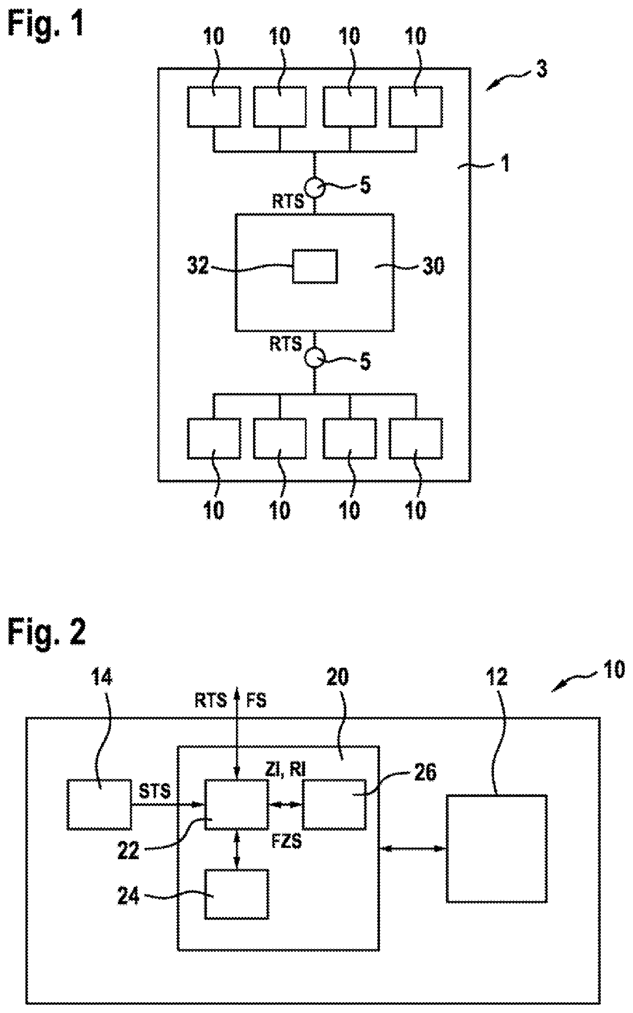
[0025]As can be seen from FIGS. 1 and 2, a sensor arrangement 3 for a vehicle 1 in the illustrated exemplary embodiment comprises a control unit 30 with a reference oscillator 32, which generates and outputs a reference clock signal RTS with a predetermined reference period duration T_ref, multiple bus nodes 5, of which two bus nodes 5 are illustrated and multiple sensor units 10, each implemented as peripheral airbag sensors and connected to one of the bus nodes 5. In the exemplary embodiment illustrated, four sensor units 10 are connected to one of the bus nodes 5. In the illustrated sensor arrangement 3, which is part of a personal protection system of the vehicle 1, the individual sensor units 10, the bus nodes 5 and the control unit 30 are connected to each other via current-modulated two-wire buses and communicate by means of the PSI5 standard. This allows the control unit 30 to receive and evaluate the pressure or acceleration data or the rotation rate data collected by the s...


PUM


Abstract

A method monitors a sensor clock signal in a sensor unit, which is generated and output for a data transfer between the sensor unit and a control unit with a predefined period duration. A reference clock signal having a predefined reference period duration is received. The sensor clock signal is compared to the reference clock signal. Based on the comparison, a deviation of the current period duration of the sensor clock signal from a target period duration is detected. Based on the detected deviation, a counting pulse or a reset pulse is emitted.

Description

[0001]The invention is based on a method for monitoring a sensor clock signal in a sensor unit according to the type of independent claim 1. The subject matter of the present invention is also a device for carrying out such a method.[0002]Peripheral Sensor Interface 5 (PSI5) is an open standard. Based on the previous PASO protocol, the PSI5 standard supports applications in which up to four sensors per bus node in different configurations can be queried by a control unit. A bidirectional communication is provided for sensor configuration and diagnostics.[0003]In airbag systems, for example, data are evaluated from pressure sensors or accelerometers that communicate with the control unit via current-modulated two-wire buses using a Manchester encoded protocol. The PSI5 standard also specifies possible operating modes. These initially differ in synchronous and asynchronous operating modes. Depending on the connection of the sensors to the control unit, the synchronous operating modes ...

Claims


Application Information

Patent Timeline
Patent Type & Authority Applications(United States)
IPC IPC(8): G01D3/08G01D18/00G06F1/12G06F1/08H03K5/19H03K5/26H04L7/00H04L7/08
CPCH04L7/0012H04L7/08G06F1/12G01D18/00H03K5/19H03K5/26G06F1/08G01D3/08G01D21/00G06F1/04
Inventor HAUG, MICHAELWEISS, GUENTERWALZ, MICHELBOMMER, DANIELASCHOU, FRANKGSCHWIND-SCHILLING, RAINERROZIC, DARKOAJANOVIC, MUSTAFACONRADT, JOERGEWERT, MARLON RAMONHAIST, KEVIN
Owner ROBERT BOSCH GMBH
Why Eureka
Try Eureka