

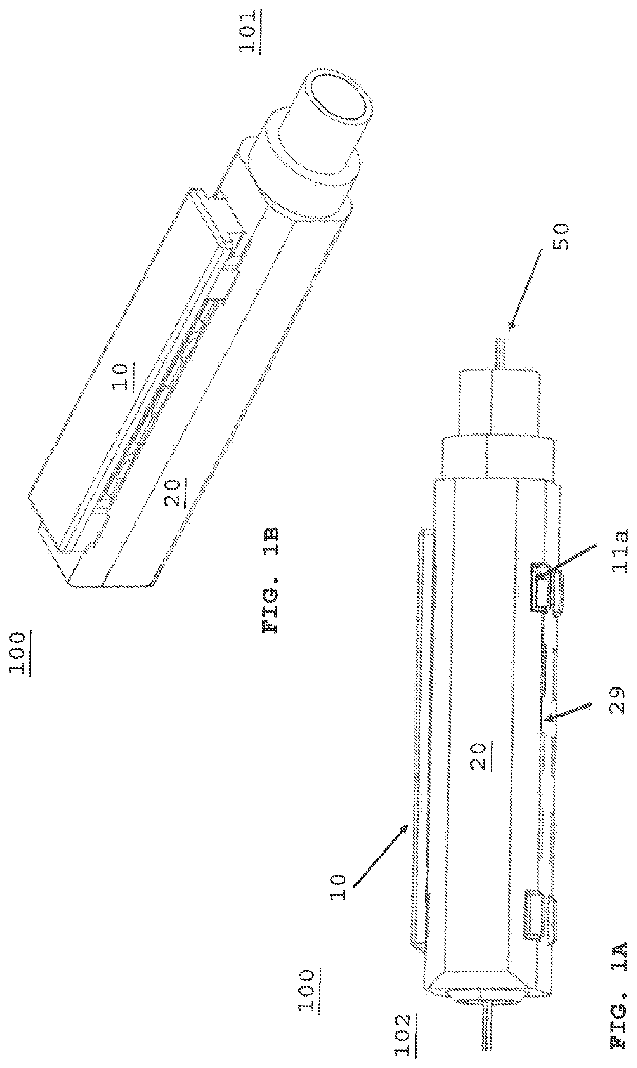
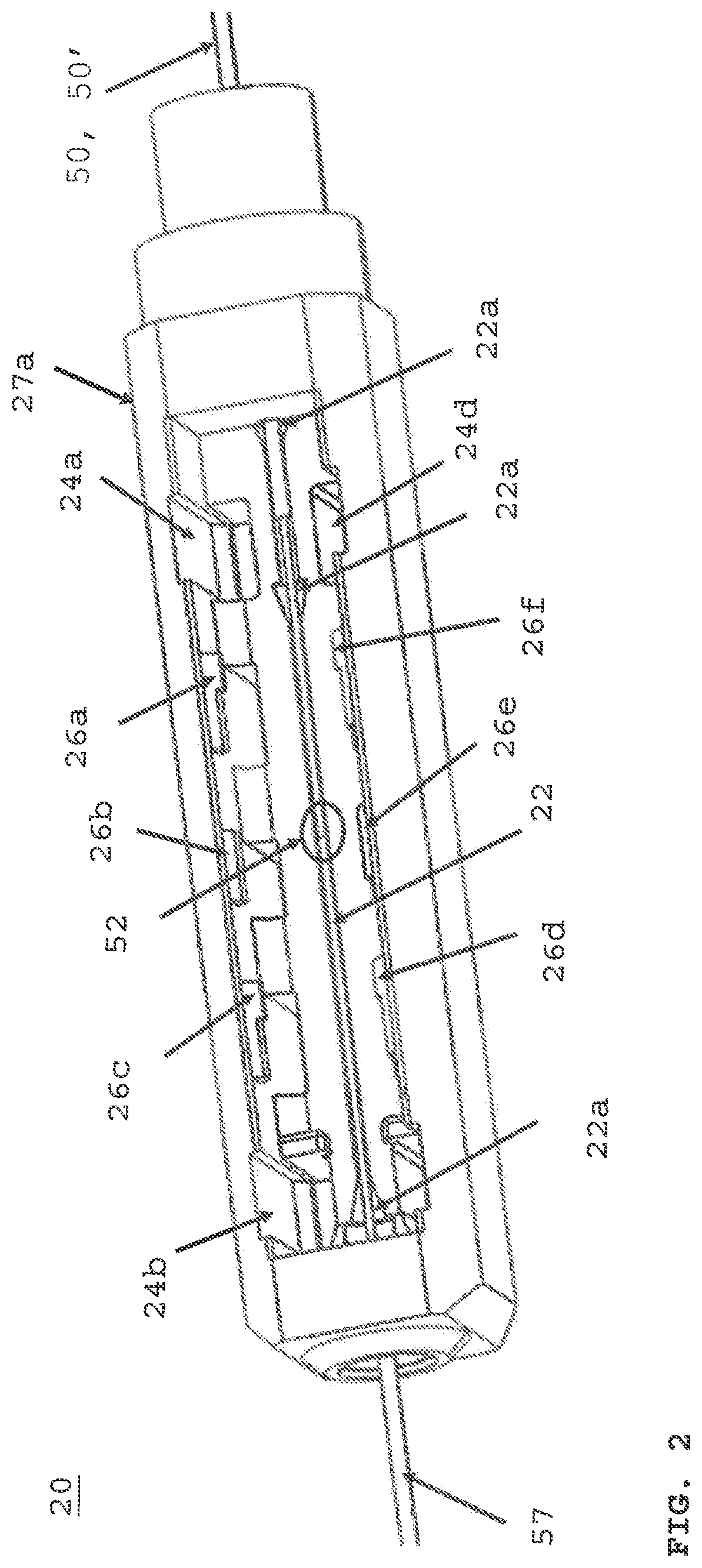
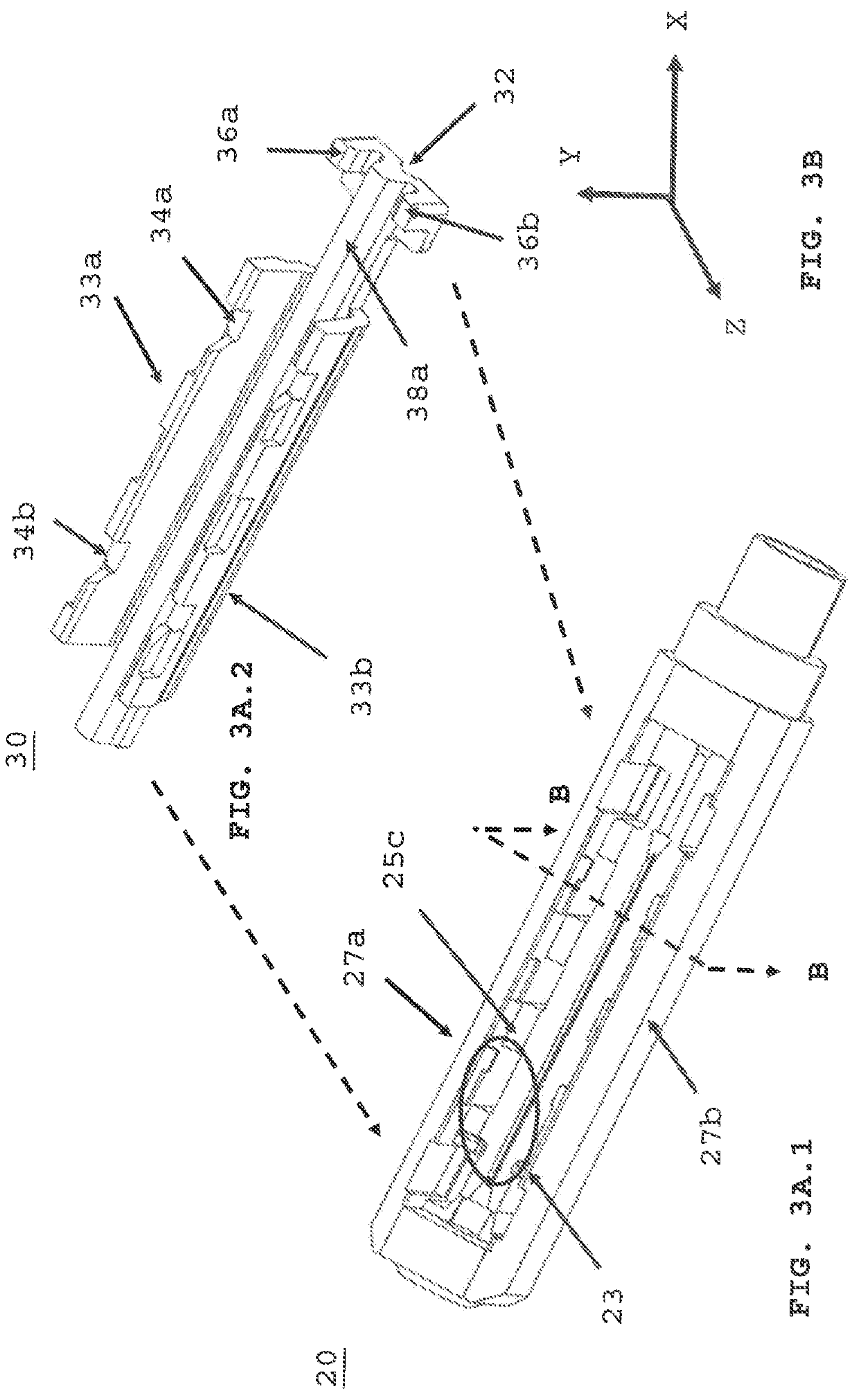
Mechanical splice assembly for splicing opposing optical fibers within a fiber optic connector and method of performing the same
a technology of optical fiber and splice assembly, which is applied in the direction of optics, instruments, optical light guides, etc., can solve the problems of increasing signal loss, and achieve the effect of preventing movement of splice optical fibers and increasing signal loss
- Summary
- Abstract
- Description
- Claims
- Application Information
AI Technical Summary
Benefits of technology
Problems solved by technology
Method used
Image

Examples
Embodiment Construction
[0048]The following terms shall have, for the purposes of this application, the respective meanings set forth below.
[0049]A connector is a device the completes a communication path from an optical fiber strand that transmits a light signal to another connector or to transceiver electronics. The electronics convert the light signal into a digital signal. A connector is inserted and secured at either end of adapter, for example, a ferrule connector (PC), a fiber distributed data interface (FDDI) connector, an LC connector, a mechanical transfer (MT) connector, a standard connector (SC) connector, an SC duplex connector, or a straight tip (ST) connector. The connector may be defined by a connector housing body, an external latch or recess to secure said connector into adapter opening and one or more ferrules having optic fibers therein. In some embodiments, the housing body may incorporate any or all of the components described herein.
[0050]A receptacle is an adapter with internal stru...
PUM
 Abstract
Description
Claims
Application Information