Millimeter wave sensor used to optimize performance of a beamforming microphone array

a millimeter wave sensor and beamforming microphone technology, applied in the field of audio systems, can solve the problems of false positives, large beam coverage positions, and the inability of dynamic beamforming to distinguish between conversations,

Active Publication Date: 2020-08-27
CRESTRON ELECTRONICS
View PDF0 Cites 32 Cited by
  • Summary
  • Abstract
  • Description
  • Claims
  • Application Information

AI Technical Summary

Benefits of technology

[0009]It is therefore a general aspect of the embodiments to provide systems, methods, and modes for systems, methods, and modes for implementing a millimeter wave sensor to optimize operation of a beamforming microphone array that will obviate or minimize problems of the type previously described.
[0144]According to the fourth aspect of the embodiments, the wave sensor system can include the object motion information about the predetermined area in the area image data signal, and wherein the method further comprises: substantially eliminating, by the adaptive beamforming circuit, fixed objects and objects moving at a substantially constant rate to determine a number of people located in the predetermined area, and output the same as a room occupancy status.

Problems solved by technology

There are primarily two types of ceiling mic arrays currently being used for audio (and video) conferencing systems, each of which exhibits significant drawbacks.
Large beam coverage positions, however, have lower S / N performance, especially for positions that are located at a significant distance from the mic array.
However, such systems are susceptible to “false positives,” meaning that a dynamic beamformer cannot distinguish between a conversation meant for the audio conference that is occurring, and the conversation that might be happening in the hallway just outside the door to the conference room.
Also, other sources of noise can cause the dynamic beams to focus on them.
Sophisticated and therefore expensive software and / or additional manual setup can diminish but not eliminate such problems.
Thus, currently available beamforming microphone arrays have limitations such as non-optimized beam forming parameters.
Beam position and area of coverage will be non-optimal.
Adaptive beamformers cannot distinguish voice from people vs. audio speakers.
As those of skill in the art can therefore appreciate, both of the primary currently available devices therefore exhibit significant drawbacks.

Method used


Image

  • Millimeter wave sensor used to optimize performance of a beamforming microphone array
  • Millimeter wave sensor used to optimize performance of a beamforming microphone array
  • Millimeter wave sensor used to optimize performance of a beamforming microphone array

Examples


Embodiment Construction

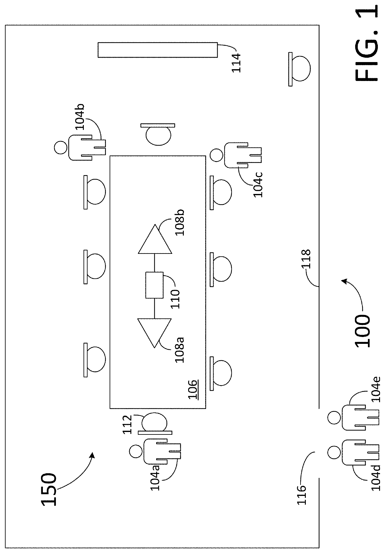
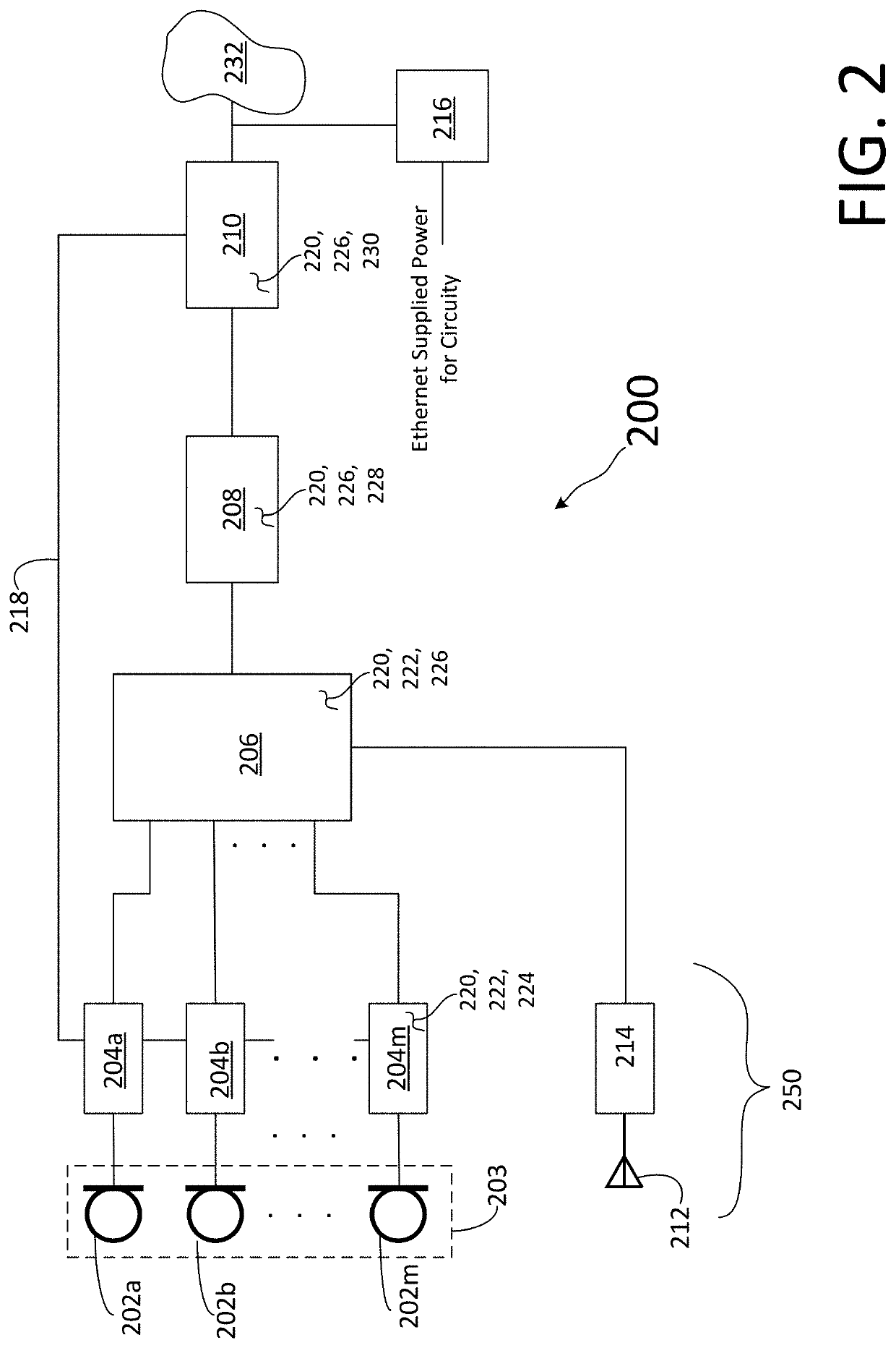
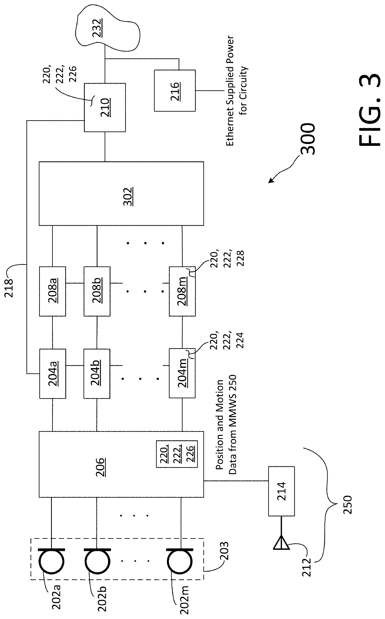
[0170]The embodiments are described more fully hereinafter with reference to the accompanying drawings, in which embodiments of the inventive concept are shown. Like numbers refer to like elements throughout. The embodiments may, however, be embodied in many different forms and should not be construed as limited to the embodiments set forth herein. Rather, these embodiments are provided so that this disclosure will be thorough and complete, and will fully convey the scope of the inventive concept to those skilled in the art. The scope of the embodiments is therefore defined by the appended claims. The detailed description that follows is written from the point of view of a control systems company, so it is to be understood that generally the concepts discussed herein are applicable to various subsystems and not limited to only a particular controlled device or class of devices, such as audio systems and related devices, audio-networking devices, and mechanical systems related to aud...


PUM


Abstract

A method for operating a beamforming microphone array for use in a predetermined area comprising: receiving acoustic audio signals at each of a plurality of microphones, converting the same to an electrical mic audio signal, and outputting each of the plurality of electrical mic audio signals; generating a user location data signal by a wave sensor system, and outputting the user location data signal, wherein the user location data signal includes location information of one or more people within the predetermined area; receiving both the user location data signal and plurality of mic audio signals at an adaptive beamforming device; adapting one or more beams by the adaptive beamforming device based on the user location data signal and plurality of output electrical mic audio signals wherein each of the one or more beams acquires sound from one or more specific locations in the predetermined area; and performing acoustic echo cancellation on each of the one or more beams output from the adaptive beamforming device.

Description

PRIORITY INFORMATION[0001]The present application claims priority under 35 U.S.C. § 119(e) to U.S. Provisional Patent Application Ser. No. 62 / 811,007, filed on Feb. 27, 2019, the entire contents of which are expressly incorporated herein by reference.CROSS REFERENCE TO RELATED APPLICATIONS[0002]Related subject matter is disclosed in the following co-pending U.S. Non-provisional patent applications: Client Matter No. CP00503-01, Serial No. XX / YYY,WWW, filed February XX, 2020; Client Matter No. CP00503-02, Serial No. XX / YYY,WWW, filed February XX, 2020; and Client Matter No. CP00503-03, Serial No. XX / YYY,WWW, filed February XX, 2020, the entire contents of all of which are expressly incorporated herein by reference.BACKGROUNDTechnical Field[0003]Aspects of the embodiments relate to audio systems, and more specifically to systems, methods, and modes for implementing a millimeter wave sensor to optimize operation of a beamforming microphone array, as well as for use in other home or ent...

Claims


Application Information

Patent Timeline
Patent Type & Authority Applications(United States)
IPC IPC(8): H04R3/00H04R1/40H04R29/00
CPCH04R29/007H04R2203/12H04R2201/403H04R3/005H04R1/406H04R2201/401G06F3/017G10L2021/02082G10L21/02G10L21/0232
Inventor LABOSCO, MARK
Owner CRESTRON ELECTRONICS
Why Eureka
Try Eureka