
Ventilation device for battery and battery comprising the same

a ventilation device and battery technology, applied in the direction of vent arrangements, batteries, cell components, etc., can solve the problems of inability to ventilate through the device, inability to produce toxic and flammable gases, and inability to achieve the effect of reducing the flow of gas through the device,

Pending Publication Date: 2020-09-03
SAMSUNG SDI CO LTD
View PDF3 Cites 5 Cited by
  • Summary
  • Abstract
  • Description
  • Claims
  • Application Information

AI Technical Summary

Benefits of technology

The present disclosure provides a combined breathing and venting device for a battery that ensures pressure balance and protects against intrusion of particles, dust fluids and humidity during normal operation. The device provides reliable gas release in a venting event and requires a low build-in space and ensures high protection against intrusion. The cover protects the venting membrane from damage or water jets. The lateral side wall of the housing has a fluid outlet for draining water that passes through the cover and accumulates on the venting membrane. The venting membrane is supported by a support structure within the breathing chamber to withstand higher pressures acting on the first surface. The breathable filter and the venting membrane rupture at a predetermined pressure to ensure safe and fast venting in a venting event.

Problems solved by technology

If such thermal management system is omitted or the heat drain from the casing is not sufficiently performed, an increase of the internal temperature can lead to abnormal reactions occurring therein.
Due to high amounts of hydrogen and carbon monoxide within the produced gas, the produced gases may be toxic and flammable.
However, breathing gas flow through these devices is strongly limited and typically these devices are not able to fulfill higher IP ratings.

Method used


Image

  • Ventilation device for battery and battery comprising the same
  • Ventilation device for battery and battery comprising the same
  • Ventilation device for battery and battery comprising the same

Examples


first embodiment

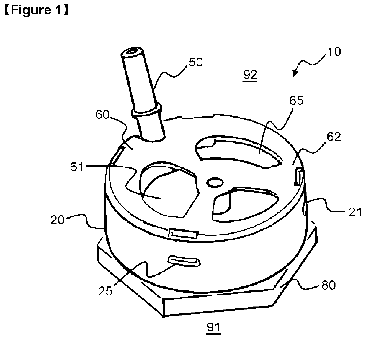
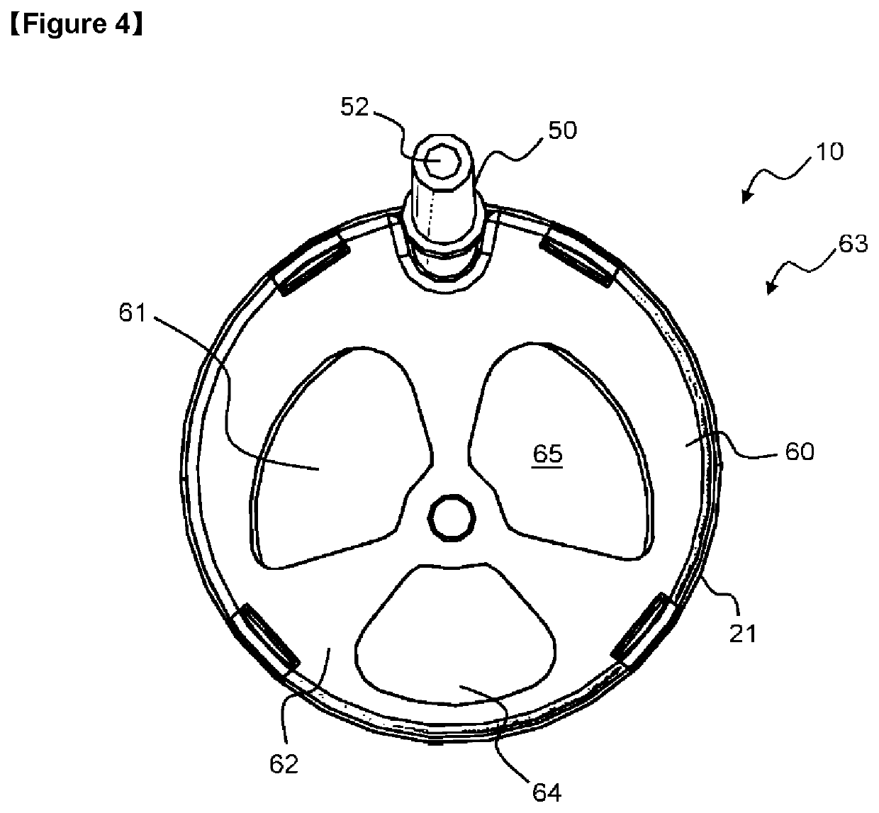
[0059]FIG. 1 illustrates a schematic perspective view of a ventilation device 10 according to a The ventilation device 10 comprises a housing 20 with an essentially cylindrical shape and a mainly solid lateral wall 21. The housing could also have an essentially rectangular shape of any other suitable shape. A cover 60 is mounted to the lateral wall 21 of the housing 20 from above and a nut 80 is mounted to housing 20 from underneath. Ventilation device 10 is mounted between a battery casing interior 91 and an exterior environment 92.

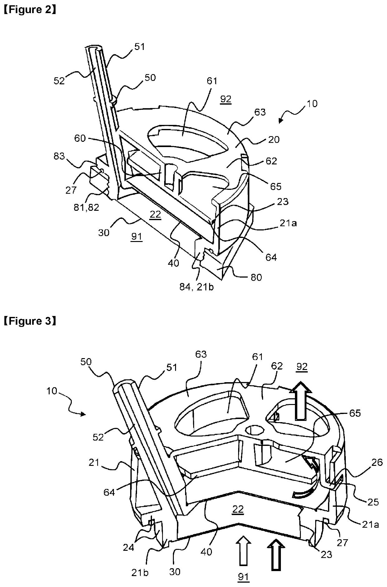
[0060]FIG. 2 illustrates a schematic perspective view of a cross section of ventilation device 10 according to the first embodiment illustrated in FIG. 1. The housing 20 comprises an upper cylindrical section 21a of a first diameter and enclosed by an upper section of lateral wall 21. The housing 20 further comprises a lower cylindrical section 21b that is enclosed by an upper section of lateral wall 21 and that has a second diameter that is smaller tha...

second embodiment

[0074]Further the ventilation device 10 of the second embodiment comprises an integrated sealing structure 28 that is formed as a single piece with the housing 20 in a two component injection molding process (2K molding). Alternatively, the separate sealing 27 as in the embodiment of FIGS. 1 to 5 could be employed. The integrated sealing structure 28 runs around the outermost perimeter of the housing 20, e.g. around the perimeter of attachment means 24. The integrated sealing structure 28 is made of a softer resin than the remaining housing 10 and comprises an essentially V-shaped cross section with the V's opening facing downward to the battery casing. By screwing the ventilation device 10 to a battery casing the sealing structure 28 is pressed to the battery casing and sealed against the battery casing. The integrated sealing structure 28 cannot be lost as the separate sealing 27.

[0075]FIGS. 8 to 11 show an alternative embodiment of a cover 60 for a ventilation device 10 according...


PUM


Abstract

The present disclosure refers to a ventilation device for a battery, particularly to a multifunctional breathing and venting device for a casing of one of a battery submodule, battery module or battery system, such as for an electric vehicle and an energy storage system (ESS). The ventilation device comprising a housing configured for being attached to a vent opening of a battery casing in a sealing manner and comprising at least one lateral wall, a breathable filter separating an interior of the battery casing from a breathing chamber within the housing, a venting membrane separating the breathing chamber from an exterior environment in a gas tight manner, and a breathing sprout fluidly connecting the breathing chamber and the environment and bypassing the venting membrane. The disclosure further relates to a battery comprising such a ventilation device attached to its casing.

Description

CROSS-REFERENCE TO RELATED APPLICATION(S)[0001]This application is a National Phase Patent Application of International Patent Application Number PCT / KR2018 / 011766, filed on Oct. 5, 2018, which claims priority of European Patent Application No. 17199096.3, filed on Oct. 30, 2017 and Korean Patent Application No. 10-2018-0118387, filed Oct. 4, 2018. The entire contents of all of which are incorporated herein by reference.TECHNICAL FIELD[0002]The present disclosure relates to ventilation device for a battery, particularly to a multifunctional breathing and venting device for a casing of one of a battery submodule, battery module or battery system that is configured for being integrated in that casing.BACKGROUND ART[0003]A rechargeable or secondary battery differs from a primary battery in that it can be repeatedly charged and discharged, while the latter provides only an irreversible conversion of chemical to electrical energy. Low-capacity rechargeable batteries are used as power sup...

Claims


Application Information

Patent Timeline
IPC IPC(8): H01M2/10H01M2/12H01M50/204H01M50/224H01M50/227H01M50/358
CPCH01M2/10H01M2/12H01M10/052H01M2220/20Y02E60/10H01M50/3425H01M50/227H01M50/224H01M50/358H01M50/204H01M50/308H01M50/394H01M50/35H01M50/20H01M50/30
Inventor WAHA, BERNHARDROECK, ALEXANDERDILLENKOFER, KIMEICHBERGER, GEORG
Owner SAMSUNG SDI CO LTD
Learn More