Methods for providing refrigeration in natural gas liquids recovery plants

Active Publication Date: 2020-09-10
LINDE ENG NORTH AMERICA
View PDF0 Cites 3 Cited by
  • Summary
  • Abstract
  • Description
  • Claims
  • Application Information

AI Technical Summary

Benefits of technology

[0011]The present invention provides for enhanced heat integration within a natural gas liquid (NGL) recovery plant to reduce

Problems solved by technology

However, liquefaction of natural gas can be problematic since some components like the heavier

Method used


Image

  • Methods for providing refrigeration in natural gas liquids recovery plants
  • Methods for providing refrigeration in natural gas liquids recovery plants
  • Methods for providing refrigeration in natural gas liquids recovery plants

Examples


Embodiment Construction

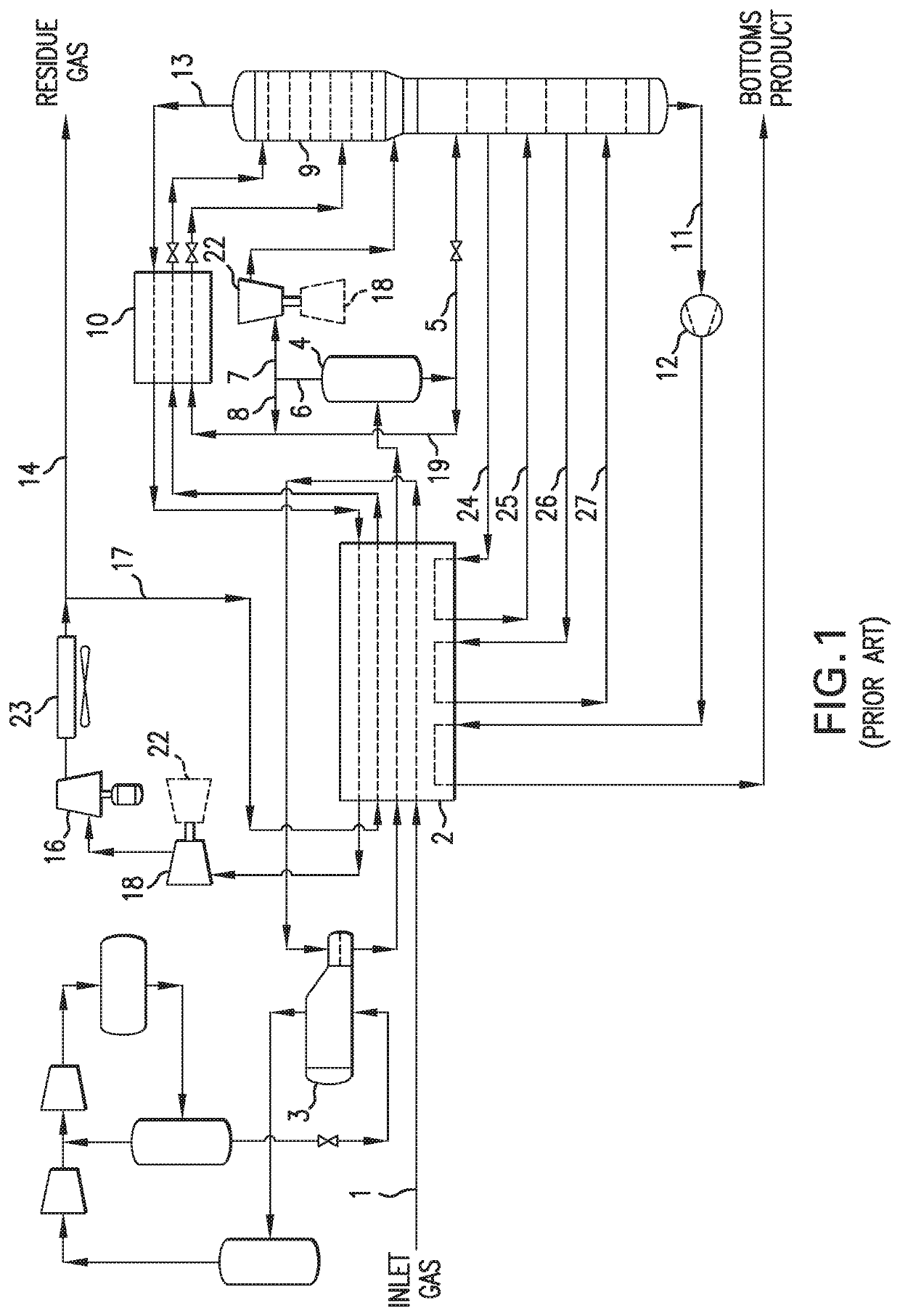
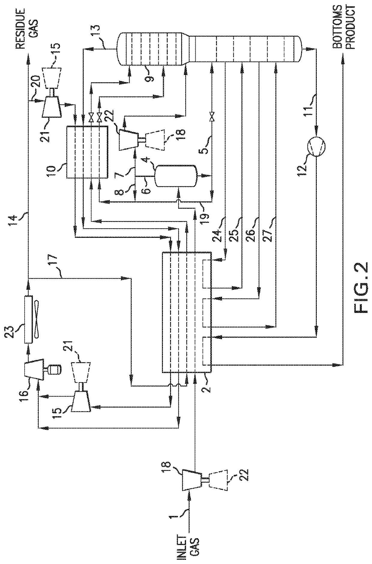
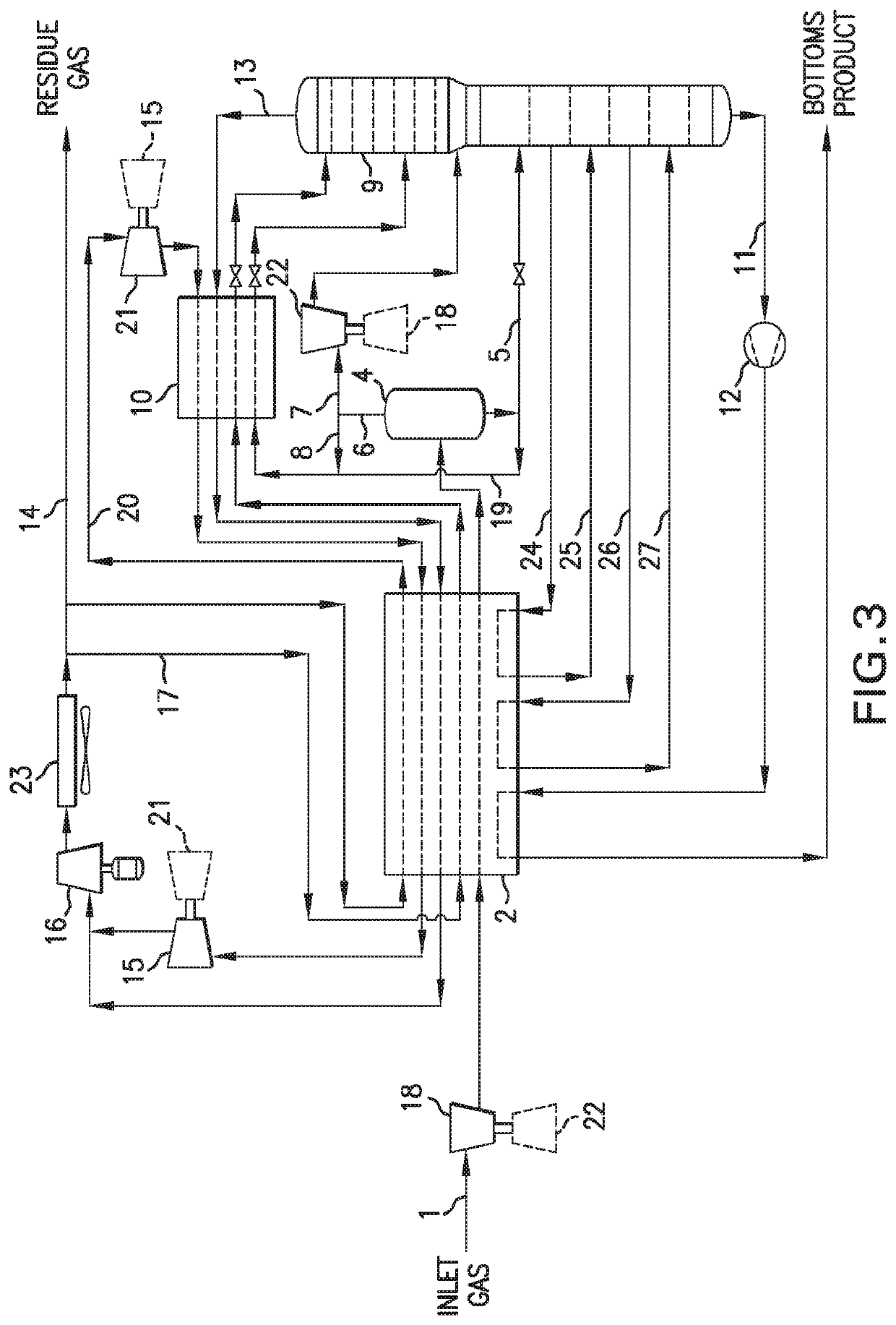
[0083]The present invention provides for the addition of an expansion unit such as a turbo-expander within a natural gas liquids recovery process or plant to allow for high pressure product gas (residue gas) to be used as a refrigerant to provide the necessary refrigeration to either of these operations.

[0084]The additional turbo-expander takes the high-pressure residue gas which is a methane-enriched or methane- and ethane-enriched gas from the discharge of the product pipeline recompression equipment (residue gas compression unit) and expands, for example, in a turbo-expander, the gas down to a pressure of between, for example, 100 and 300 psig. The resultant cold refrigerant gas then passes through the overhead heat exchanger and the main heat exchanger(s) and then preferably utilizes the energy from the expansion of the residue gas to boost the pressure of the resultant heated refrigerant gas back to the inlet of the product pipeline recompression equipment.

[0085]The advantages ...


PUM


Abstract

A process and plant for natural gas liquids (NGL) recovery includes a main heat exchanger, a cold gas/liquid separator, a separation or distillation column, and an overhead gas heat exchanger. A pressurized residue gas generated from an overhead gas stream removed the top of the separation or distillation column is expanded and used as a cooling medium in the overhead gas heat exchanger and the main heat exchanger. The expanded residue gas, used as a cooling medium, is then compressed up to a pressure to be combined with the overhead stream from the separation or distillation column.

Description

[0001]This applicant claims the benefit under 35 U.S.C. 119(e) of U.S. provisional application Ser. No. 62 / 544,633, filed Sep. 6, 2017.BACKGROUND OF THE INVENTION[0002]Natural gas is an important commodity throughout the world, as both an energy source and a source of raw materials. Worldwide natural gas consumption is projected to increase from 124 trillion cubic feet in 2015 to 177 trillion cubic feet in 2040 [U.S Energy Information Administration, International Energy Outlook 2017 (IEO2017)].[0003]Natural gas is important not only as a source of energy but also as a source of feedstock for petrochemical manufacture. In general, natural gas is recovered from onshore and offshore oil and gas production wells. The major component of natural gas is typically methane. But, natural gas also contains amounts of other hydrocarbons such as ethane, propane, butanes, pentanes and heavier components. In addition to the hydrocarbon components, natural gas can also contain small amounts of wat...

Claims


Application Information

Patent Timeline
IPC IPC(8): F25J3/02
CPCF25J2290/40F25J3/0295F25J2200/30F25J2270/88F25J2200/72F25J3/0209F25J2240/40F25J2240/02F25J2215/60F25J3/0233F25J2215/04F25J2215/64F25J3/0238F25J2270/04F25J2230/30F25J2205/04F25J2210/60F25J2215/62F25J2230/60F25J2200/76F25J3/0242F25J2200/02C10L2290/06C10L2290/543C10L3/10C10L2290/48
Inventor MCCOOL, GRANTWALTER, THOMASPUIGBO, ARTURO
Owner LINDE ENG NORTH AMERICA
Why Eureka
Try Eureka