Supercharge Your Innovation With Domain-Expert AI Agents!

System for non-contact transmission of electrical energy to a mobile part

a non-contact transmission and mobile technology, applied in the direction of electric vehicle charging technology, charging stations, transportation and packaging, etc., can solve the problem that sheet metal parts can be produced in an uncomplicated and cost-effective manner

Active Publication Date: 2020-09-10
SEW-EURODRIVE GMBH & CO KG
View PDF0 Cites 2 Cited by
  • Summary
  • Abstract
  • Description
  • Claims
  • Application Information

AI Technical Summary

Benefits of technology

This patent describes a design that improves heat dissipation in electronic circuits. The design uses a sheet-metal part that is connected to a concrete frame, which ensures good thermal conduction. The sheet-metal part is made from corrugated sheet metal, which is cost-effective and easy to produce. The design also ensures voltage-proof electrical insulation by using plastic for the cover part. The cover part is made from plastic, which allows for smooth movement of the mobile part across the cover part while providing insulation resistance.

Problems solved by technology

In addition, the sheet-metal part is able to be produced in an uncomplicated and cost-effective manner from corrugated sheet metal so that linear contact is provided both radially outside and inside in each case.

Method used


Image

  • System for non-contact transmission of electrical energy to a mobile part
  • System for non-contact transmission of electrical energy to a mobile part

Examples


Embodiment Construction

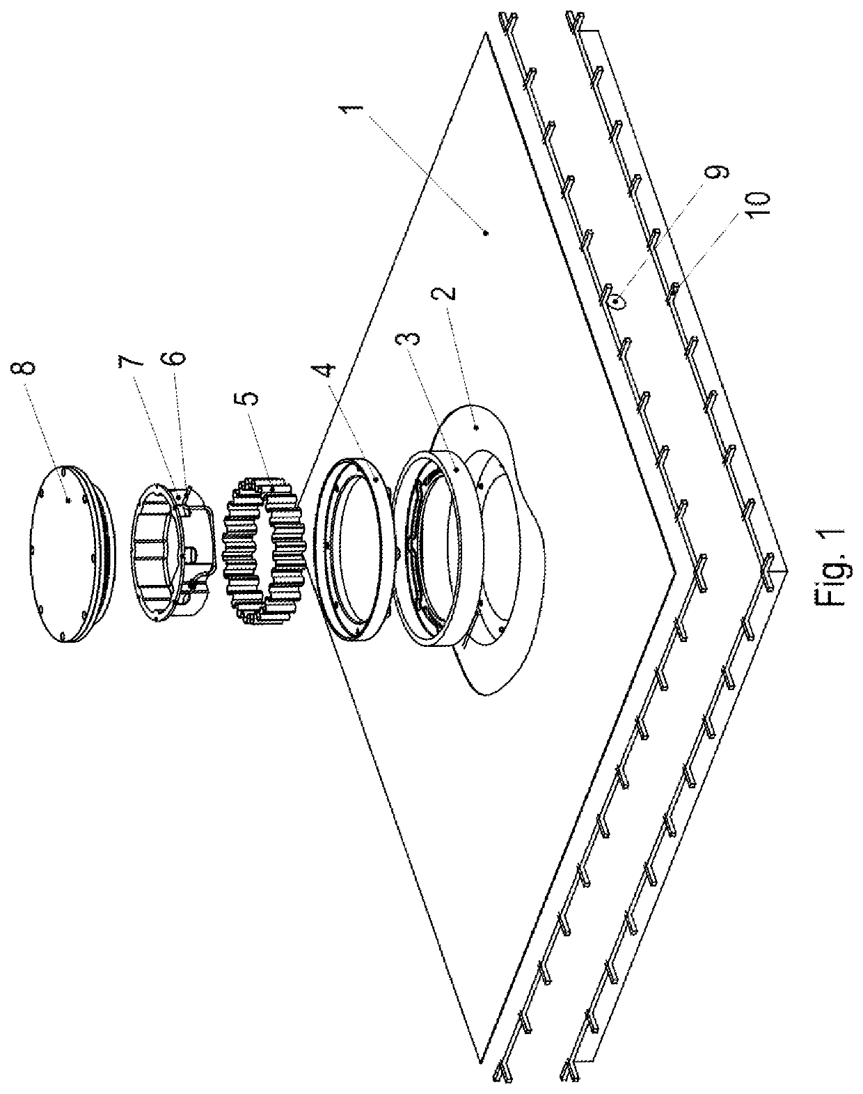
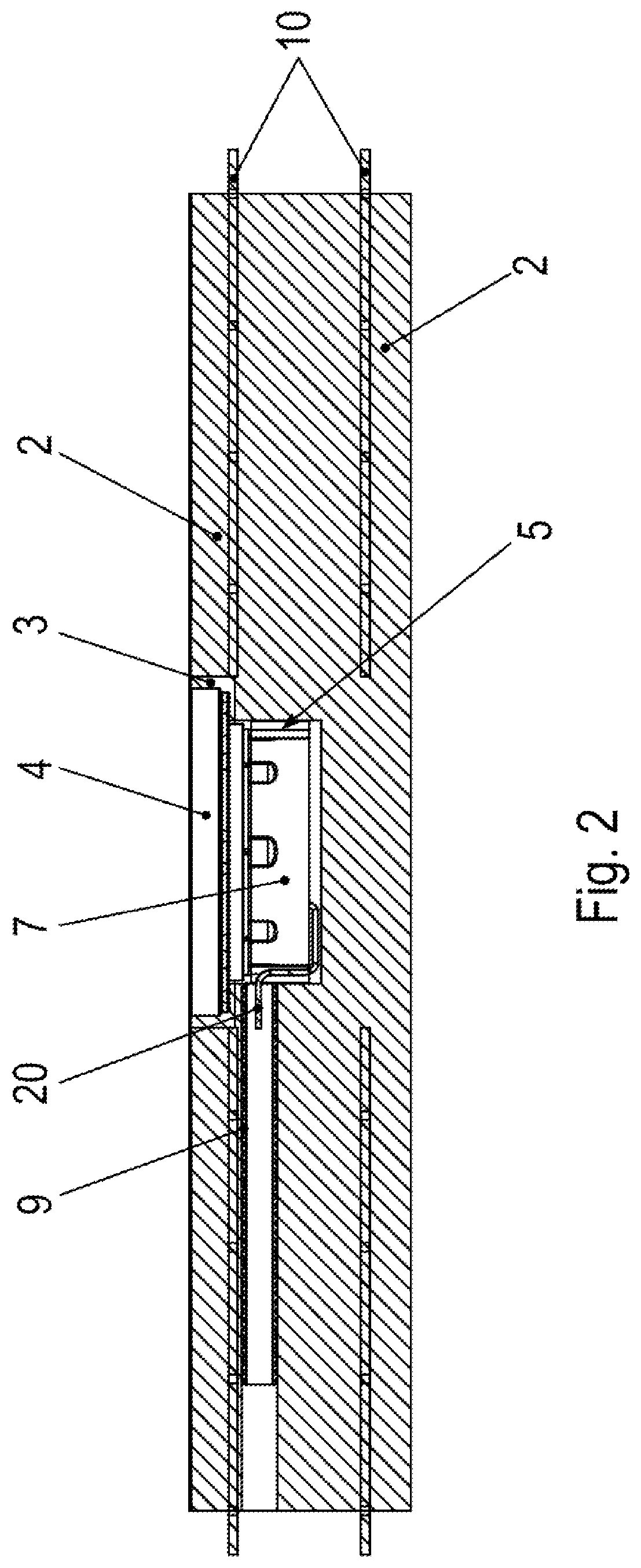
[0023]As schematically illustrated in FIGS. 1 and 2, floor material 2 of the floor of a system is provided with a coating 1 whose surface functions as a travel surface for a mobile part.

[0024]Situated on the underside of the mobile part is a secondary winding, which is able to be inductively coupled to a primary winding situated on the floor at a position of the mobile part.

[0025]Reinforcement 10 made of steel rods is situated in floor material 2 as well as an empty conduit in which a cable 6 is routed to a charging unit, which is situated in a bore, in particular a stepped bore, introduced into the floor material.

[0026]A frame part 4, which is integrally connected to floor material 2 with the aid of casting compound 3, is placed on the step of the recess arranged as a stepped bore.

[0027]A receiving part 7, which is made of plastic, is situated in the frame part, and a sheet-metal part 5, which touches both frame part 4 and receiving part 7, is situated between frame part 4 and rece...


PUM

PropertyMeasurementUnit
electrical energyaaaaaaaaaa
frequencyaaaaaaaaaa
capacitanceaaaaaaaaaa

Abstract

In a system for a non-contact transmission of electrical energy to a mobile part, the system has a bore introduced into a floor material, a frame part is accommodated in the bore, a receiving part is situated in the frame part, an electronic circuit is situated in the receiving part, the receiving part is at least partially covered by a cover part in the manner of a housing, in particular on one of its sides, a sheet-metal part is situated between the receiving part and the frame part, and the sheet-metal part touches the receiving part and the sheet-metal part touches the frame part.

Description

FIELD OF THE INVENTION[0001]The present invention relates to a system for a non-contact transmission of electrical energy to a mobile part.BACKGROUND INFORMATION[0002]U.S. Patent Application Publication No. 2014 / 0240947 describes a power-receiving device.[0003]PCT Patent Application Publication No. WO 2011 / 117714 describes a system for a non-contact transmission of electrical energy.[0004]Japanese Patent Application Publication No. 2012-222956 describes a system for a non-contact transmission of electrical energy.[0005]U.S. Patent Application Publication No. 2012 / 0218068 describes an antenna.[0006]U.S. Patent Application Publication No. 2017 / 0237295 describes a system for a non-contact transmission of electrical energy.[0007]U.S. Pat. No. 5,528,113 describes a system for an inductive transmission of electrical energy.[0008]U.S. Patent Application Publication No. 2014 / 0361635 describes a system for a non-contact transmission of energy.SUMMARY[0009]Example embodiments of the present i...

Claims


Application Information

Patent Timeline
Patent Type & Authority Applications(United States)
IPC IPC(8): H02J50/00H02J50/10B60L53/30H01F27/02H01F38/14
CPCH02J50/005H02J50/10H01F38/14H01F27/02B60L53/30H01F27/025B60L53/12B60L2270/147Y02T10/70Y02T10/7072Y02T90/14Y02T90/12
Inventor JAHN, NILS-MALTEKREMPEL, THOMASEGGER, BJÖRN
Owner SEW-EURODRIVE GMBH & CO KG
Features
  • R&D
  • Intellectual Property
  • Life Sciences
  • Materials
  • Tech Scout
  • Unparalleled Data Quality
  • Higher Quality Content
  • 60% Fewer Hallucinations
Learn More