Particle detecting device

Active Publication Date: 2020-09-17
MICROJET TECH
View PDF0 Cites 8 Cited by
  • Summary
  • Abstract
  • Description
  • Claims
  • Application Information

AI Technical Summary

Benefits of technology

[0004]An object of the present disclosure provides a particle detecting device. A detecting channel and a beam channel are defined and partitioned in a slim base, and a laser transmitter and a particle sensor of the detecting element and the micro pump are positioned in the base. With the help of micro pump, the gas is transported along the detecting channel, which is a straight gas-flowing path. Thus, the introduced gas can pass through the orthogonal position where the detecting channel intersects the beam channel smoothly and steadily, and the size and concentration of the suspended particles contained in the gas can be detected. In addition, the light trapping structure of the light trapping region is a paraboloidal structure, and the light trapping distance between the beam channel and the position where the light trapping structure receives the projecting light source from the light transmitter is maintained to

Problems solved by technology

Since the sizes of the suspended particles are really small, the suspended particles may enter the lungs of human body through the nasal hair in the nasal cavity easily, thus causing inflammation in the lungs, asthma or cardiovascular disease.
If other pollutants are attached to the suspended particles, it will further increase the harm to the respiratory system.
In recent years, the problem of

Method used


Image

  • Particle detecting device
  • Particle detecting device
  • Particle detecting device

Examples


Embodiment Construction

[0020]The present disclosure will now be described more specifically with reference to the following embodiments. It is to be noted that the following descriptions of preferred embodiments of this invention are presented herein for purpose of illustration and description only. It is not intended to be exhaustive or to be limited to the precise form disclosed.

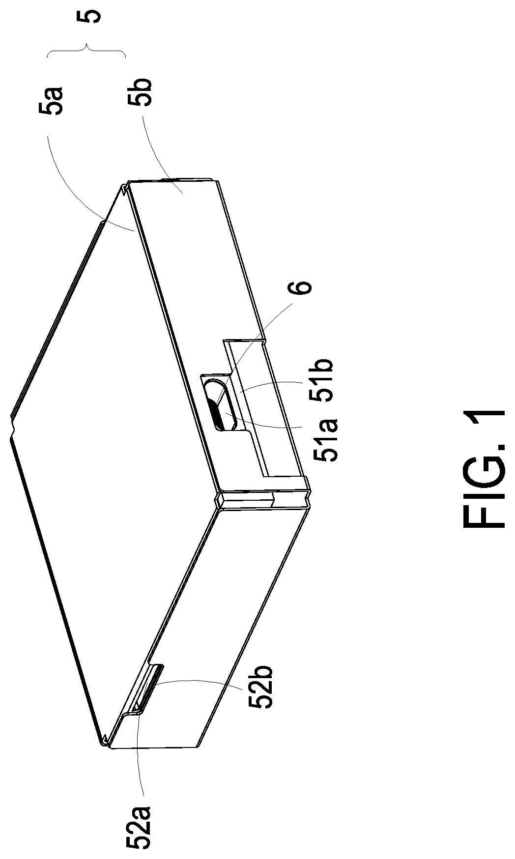
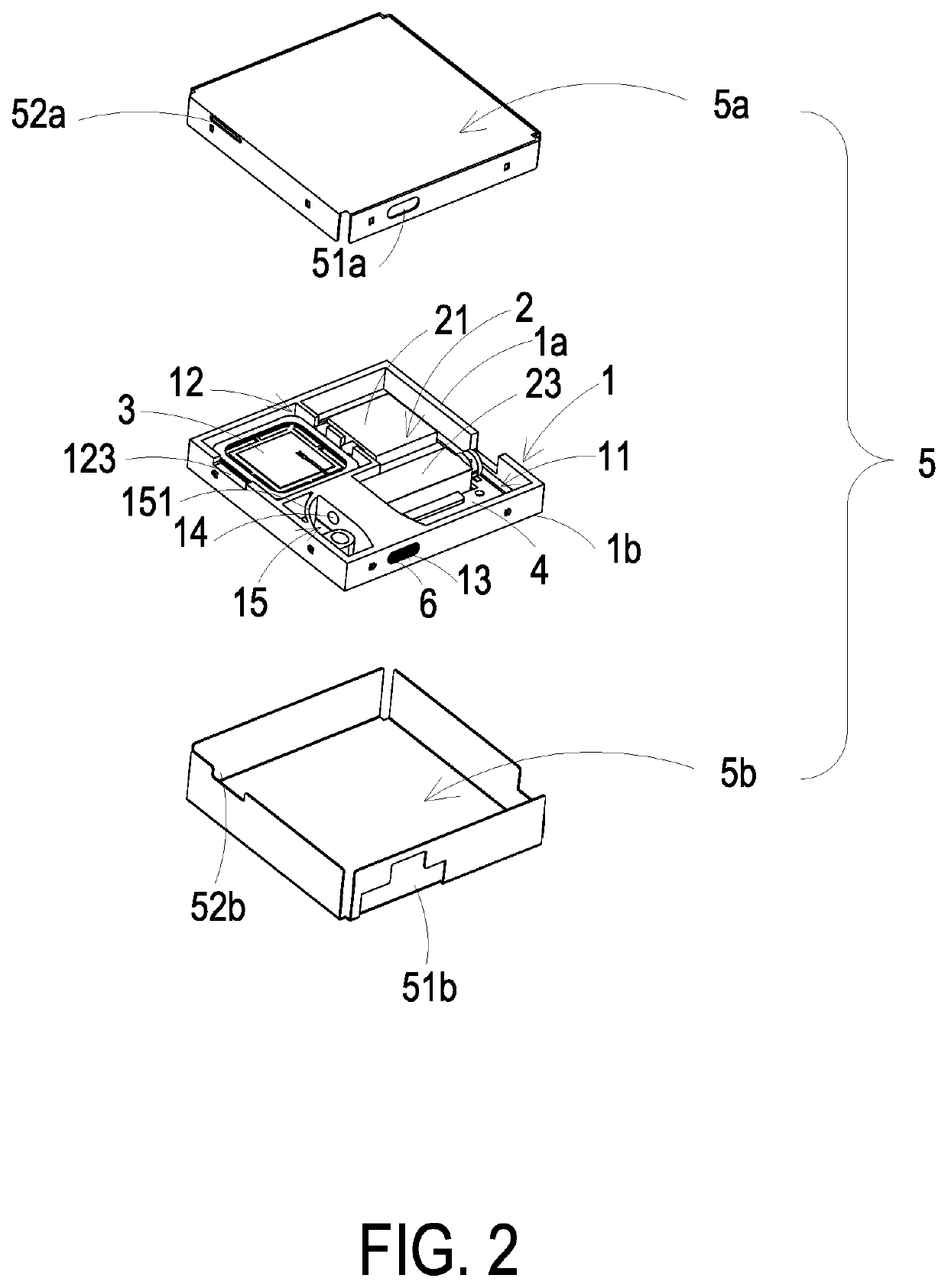
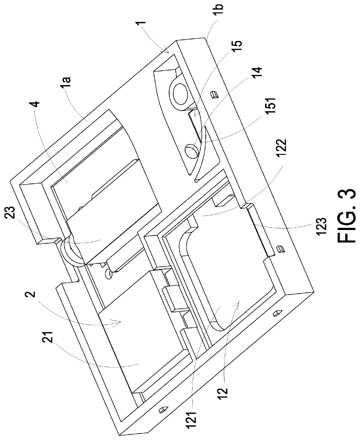
[0021]Please refer to FIGS. 1 to 4C. The present disclosure provides a particle detecting device including a base 1, a detecting element 2, a micro pump 3, a drive control board 4, an outer cover 5 and a protective film 6. The base 1 has a first surface 1a and a second surface 1b, and the first surface 1a and the second surface 1b are two surfaces opposite to each other. A detecting-element accommodation region 11, a micro-pump accommodation region 12, a detecting channel 13, a beam channel 14 and a light trapping region 15 are defined and partitioned inside the base 1. The detecting channel 13 and the beam channel 14 are perpen...


PUM


Abstract

A particle detecting device is provided. The particle detecting device includes a base, a detecting element, a micro pump and a drive control board. The base includes a detecting channel, a beam channel and a light trapping region. The detecting element includes a microprocessor, a particle sensor and a laser transmitter. The particle sensor is disposed at an orthogonal position where the detecting channel intersects the beam channel. When the micro pump, the particle sensor and the laser transmitter are enabled under the control of the microprocessor, the gas outside the detecting channel is inhaled into the detecting channel. When the gas flows to the orthogonal position where the detecting channel intersects the beam channel, the gas is irradiated by the projecting light source from the laser transmitter, and projecting light spots generated are projected on the particle sensor for detecting the size and the concentration of suspended particles.

Description

FIELD OF THE INVENTION[0001]The present disclosure relates to a particle detecting device, and more particularly to a particle detecting device capable of being assembled to a slim portable device for gas monitoring.BACKGROUND OF THE INVENTION[0002]Suspended particles are solid particles or droplets contained in the air. Since the sizes of the suspended particles are really small, the suspended particles may enter the lungs of human body through the nasal hair in the nasal cavity easily, thus causing inflammation in the lungs, asthma or cardiovascular disease. If other pollutants are attached to the suspended particles, it will further increase the harm to the respiratory system. In recent years, the problem of air pollution is getting worse. In particular, the concentration of particle matters (e.g., PM2.5) is often too high. Therefore, the monitoring to the concentration of the gas suspended particles is taken seriously. However, the gas flows unstably due to variable wind directi...

Claims


Application Information

Patent Timeline
IPC IPC(8): G01N15/06G01N15/02
CPCG01N15/0656G01N15/02G01N2015/0007F04B43/046F04B45/047G01N15/0211G01N15/06G01N15/1459G01N2015/0046G01N2015/0693G01N2015/1486
Inventor MOU, HAO-JANWU, CHIN-CHUANCHEN, CHIH-KAILIN, CHING-SUNGHUANG, CHI-FENGHAN, YUNG-LUNGKUO, CHUN-YI
Owner MICROJET TECH
Why Eureka
Try Eureka