Vibrating machine with a bearing device and method of operating a vibrating machine

a technology of bearing device and vibrating machine, which is applied in the field of vibrating machines, can solve the problems of air not being given sufficient time to balance out the pressure, and achieve the effects of preventing the displacement of the vibrating second machine part, low damping, and reducing the stiffness level

Active Publication Date: 2020-09-24
SPALECK GMBH & CO KGAA
View PDF0 Cites 5 Cited by
  • Summary
  • Abstract
  • Description
  • Claims
  • Application Information

AI Technical Summary

Benefits of technology

[0019]The particular advantage of the invention resides in the fact that an increased displacement of the vibrating second machine part is prevented or at least markedly reduced during the startup and rundown of the vibrating machine and the inevitably occurring sweep through the natural frequency of the bearing device. This is accomplished by the damping effected by the compressed air reservoir fluidically connected to the air spring and by the throttle installed in the fluidic connection and connected between the air spring and the compressed air reservoir. The bearing device according to the invention can also be advantageously used at high vibration amplitudes such as 20 mm, and is essentially wear-free.
[0020]A frequency-dependent, dynamic stiffness and damping of the bearing device of the vibrating machine can be achieved with the throttle. The dynamic stiffness exhibits a pronounced increase with rising frequency until an upper stiffness level with low damping is reached. The behavior in this case corresponds to that of an individual, stiff air spring. The lower stiffness level with large damping results from artificially enlarging the volume of the air spring by adding the volume of the compressed air reservoir. A transition zone in which the bearing device is increasingly stiffened lies between the upper and lower stiffness levels. Hence a transitional frequency can be determined from this at the turning point of the curve, which describes the point in time from which the additional volume in the compressed air reservoir is gradually decoupled from the air spring. Advantageously, the coupling and decoupling are performed automatically by physical effects without the necessity of active control of the throttle or other components of the bearing device. The decoupling already takes place due to the fact that at high frequencies and with a throttle having a correspondingly dimensioned throughput cross-section, the air is not given sufficient time to balance out the pressure between the air spring and the additional volume in the compressed air reservoir. Accordingly, the damping drops to a negligible level after decoupling in operation of the relevant vibrating machine with a nominal rotary speed and does not negatively influence the energy efficiency of the vibrating machine. If a suitable throttle is selected, the transitional frequency lies close to, preferably slightly above, the resonant or natural frequency of the first vibratory machine part of the vibrating machine, whereby the maximum damping desired here is produced for this frequency range.
[0021]As simulations and practical trials have shown, two-digit degrees of damping, approaching 20%, are obtained when optimal parameters of the bearing device and particularly of the throttle cross-section are selected. By this means, there is a significant reduction in vibration amplitudes, i.e., excessive vibration during startup and rundown, of the vibratory machine part of the relevant vibrating machine during the resonance sweep and hence in the dynamic loads of the vibrating machine, the bearing device, and also of the surrounding area. As opposed to this, vibrating machines mounted on conventional air springs known from the prior art or on steel springs with equivalent damping properties have excessive vibrations amounting to a multiple of the stationary vibration amplitude.
[0022]The natural or resonant frequency of the bearing device of the vibrating machine according to the invention lies at an advantageously low level conditioned by its technical functioning principle; for example, in practice this would preferably be between approximately 1 and 3 Hz. Therefore, even with relatively slow vibrating machines, i.e., those running at a low operating frequency of down to approximately 8 Hz, for example, the distance between the natural or resonant frequency of the bearing device and the operating frequency of the vibrating machine is adequate. Hence, even at operating frequencies as low as 8 Hz, the vibration isolation is adequate.
[0023]The bearing device of the vibrating machine according to the invention thus represents a system of air-spring-and-damper unit that produces damping in a desired frequency range via physical, thermodynamic and fluid-dynamic effects by means of an air spring with an additional volume, connected through a throttle. The damping occurs through energy dissipation in the form of heat, which can be verified by measurements made using a thermal imaging camera on a bearing device according to the invention.
[0024]A first embodiment of the vibrating machine with bearing device provides that the throttle is not adjustable. This bearing device of the vibrating machine is distinguished by a technically especially simple and thus inexpensive design since a non-adjustable throttle contains no movable elements susceptible to wear and no additional active elements such as actuators. Nevertheless, the favorable features and advantages described above are already achieved in this technically simple bearing device of the vibrating machine.

Problems solved by technology

The decoupling already takes place due to the fact that at high frequencies and with a throttle having a correspondingly dimensioned throughput cross-section, the air is not given sufficient time to balance out the pressure between the air spring and the additional volume in the compressed air reservoir.

Method used


Image

  • Vibrating machine with a bearing device and method of operating a vibrating machine
  • Vibrating machine with a bearing device and method of operating a vibrating machine
  • Vibrating machine with a bearing device and method of operating a vibrating machine

Examples


Embodiment Construction

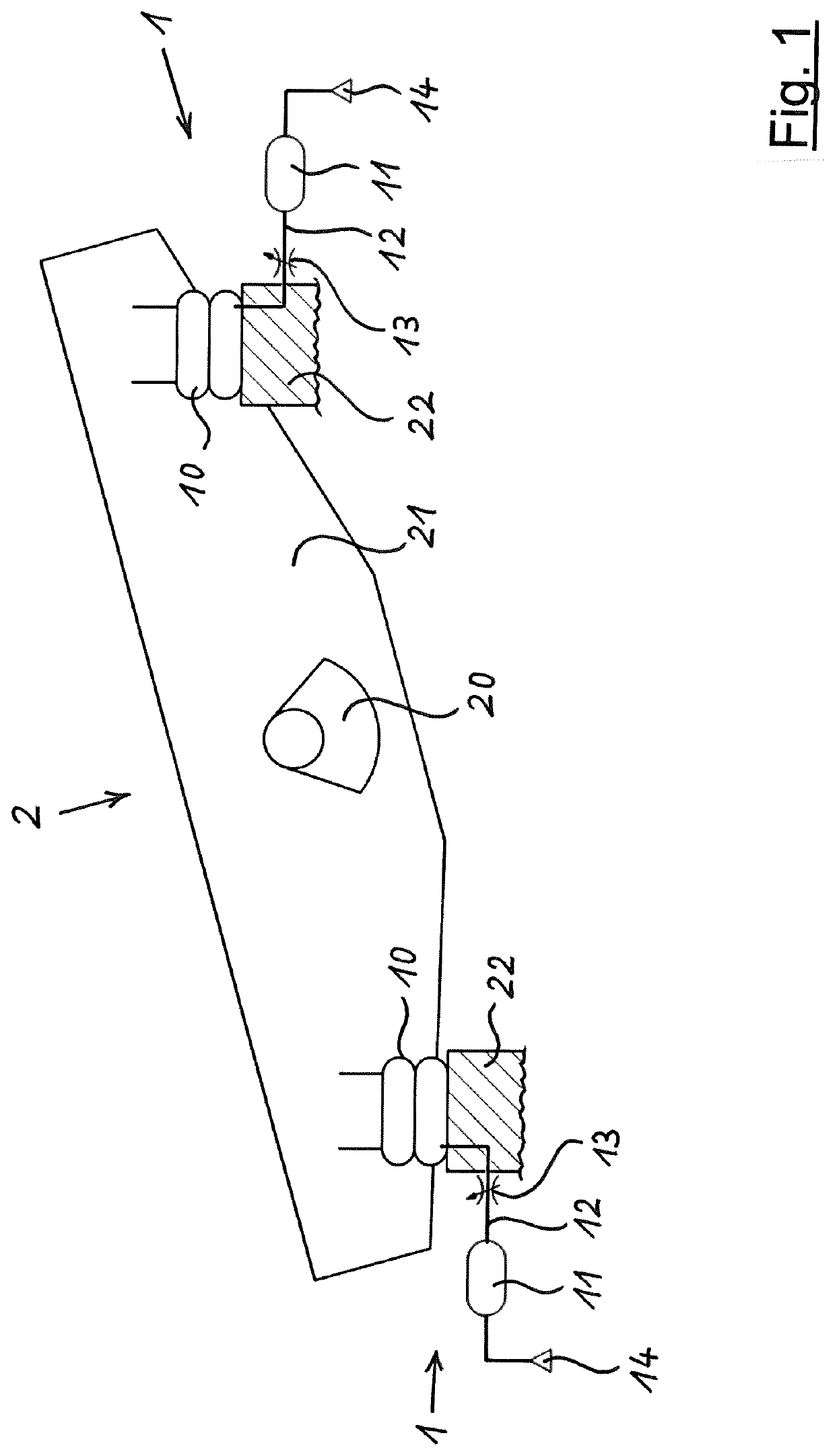
[0059]FIG. 1 shows a schematic drawing of a vibrating machine 2, such as a screening machine or vibratory conveyor, having a first bearing device 1. The vibrating machine 2 has a first machine part 21 that vibrates in operation, a second machine part 22 connected to an installation surface of the vibrating machine 2 and a vibration drive 20 such as an eccentric mass set into vibration by a rotary drive, as indicated in FIG. 1 and as is known per se. A screening or conveyor surface is hidden behind the visible part of the first machine part 21 in FIG. 1 and is likewise known per se.

[0060]A resilient bearing device 1 is arranged between the machine parts 21, 22 to make the vibration of the first machine part 21 possible relative to the second machine part 22 and to decouple the vibrations of the first machine part 21 from the second machine part 22 and from the installation surface and the environment.

[0061]The bearing device 1 has one air spring 10 per support point. Two front suppor...


PUM


Abstract

A vibrating machine including a first machine part that vibrates in operation, a second machine part connected to an installation area of the vibrating machine, and a vibratory drive. A resilient bearing is arranged between the machine parts and has at least one air spring per support point and at least one compressed air reservoir fluidically connected to the air spring. A throttle is switched intermediate the air spring and the compressed air reservoir. The first machine part bearing has a resonant or natural frequency lower than an operating frequency of the vibrating machine. The bearing system has a frequency-dependent lower stiffness level with high damping at low frequencies, an upper stiffness level with low damping at higher frequencies, and a transition zone at an intermediate transitional frequency. The throttle is dimensioned such that the transitional frequency is close to, preferably slightly above, the resonant or natural frequency.

Description

CROSS-REFERENCES TO RELATED APPLICATIONS[0001]This application claims the benefit of the International Application No. PCT / EP2018 / 081330, filed on Nov. 15, 2018, and of the German patent application No. 10 2017 128 230.0 filed on Nov. 29, 2017, the entire disclosures of which are incorporated herein by way of reference.FIELD OF THE INVENTION[0002]The invention relates to a vibrating machine comprising a first machine part that vibrates in operation; a second machine part connected to an installation area of the vibrating machine; and a vibratory drive, wherein a resilient bearing device is arranged between the machine parts and has at least one air spring per support point and at least one compressed air reservoir fluidically connected to the air spring, and wherein a throttle is switched in between the air spring and the compressed air reservoir. The invention also relates to a method of operating a vibrating machine.BACKGROUND OF THE INVENTION[0003]In vibrating machines, such as s...

Claims


Application Information

Patent Timeline
Patent Type & Authority Applications(United States)
IPC IPC(8): F16F15/027F16F15/023B65G27/32
CPCB65G27/32F16F15/0275F16F15/0232B07B1/42F16F15/027B65G27/20B65G2207/40
Inventor HALLADIN, JÖRGLOHSCHELLER, NIKLAS
Owner SPALECK GMBH & CO KGAA
Why Eureka
Try Eureka