Photovoltaic lighting system having integrated control board, and monitoring system using same

a photovoltaic lighting and control board technology, applied in lighting and heating apparatuses, instruments, and power systems with built-ins, etc., can solve the problems of insufficient situation handling, inability to check history information, and increase maintenance and repair costs, so as to improve charging efficiency and reduce the number of parts , the effect of rapid situation handling

Active Publication Date: 2020-09-24
CHORUSING
View PDF0 Cites 6 Cited by
  • Summary
  • Abstract
  • Description
  • Claims
  • Application Information

AI Technical Summary

Benefits of technology

[0018]Accordingly, the present invention can have effects in that power generation and charging efficiency are improved by estimating a maximum power point and controlling the charging and discharging of a battery.
[0019]Furthermore, the present invention can have effects in that rapid situation handling is possible, the number of parts is reduced, and the number of assembly processes is reduced because conventional separated elements can be integrated into one and controlled through the integrated control board.
[0020]Furth...

Problems solved by technology

For example, a known streetlamp has a problem in that maintenance and repair costs are increased because externally supplied commercial AC power is used as a power source.
In the streetlamp system, history information cannot be checked upon trouble shooting, and situation handling is insufficient when a failure actually occurs.
However, if the battery is discharged due to the shortage of a solar radiation quantity, the streetlamp is turned on by power supplied by an external system or maintains a turn-off state.
That is, conventionally, an implementation of the independent type lighting system using new renewable energy is limited because a light is not maintained by only sunlight and the lighting system is substantially inevitably associated with an external system.
Fur...

Method used


Image

  • Photovoltaic lighting system having integrated control board, and monitoring system using same
  • Photovoltaic lighting system having integrated control board, and monitoring system using same
  • Photovoltaic lighting system having integrated control board, and monitoring system using same

Examples


Embodiment Construction

[0030]The present invention may be changed in various ways and may have various embodiments, and specific embodiments of the various embodiments are illustrated in the drawings and described in detail.

[0031]It is to be understood that the present invention is not intended to be limited to the specific present invention and that the present invention corresponds to any one of all changes, equivalents to substitutions included in the spirit and technological scope of the present invention for connecting and / or fixing structures extended in different directions.

[0032]The terms used in this specification are used to only describe a specific embodiment and are not intended to restrict the present invention. An expression of the singular number includes an expression of the plural number unless clearly defined otherwise in the context.

[0033]In the specification, it is to be understood that a term, such as “include” or “have”, is intended to designate that a characteristic, number, step, o...


PUM


Abstract

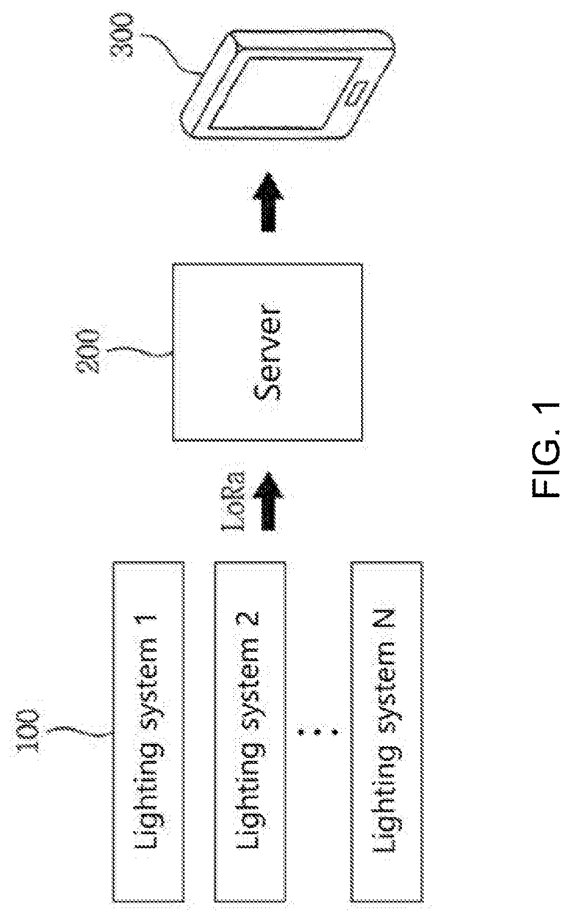
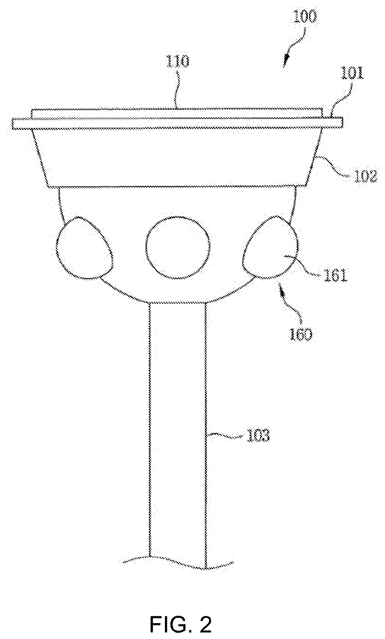
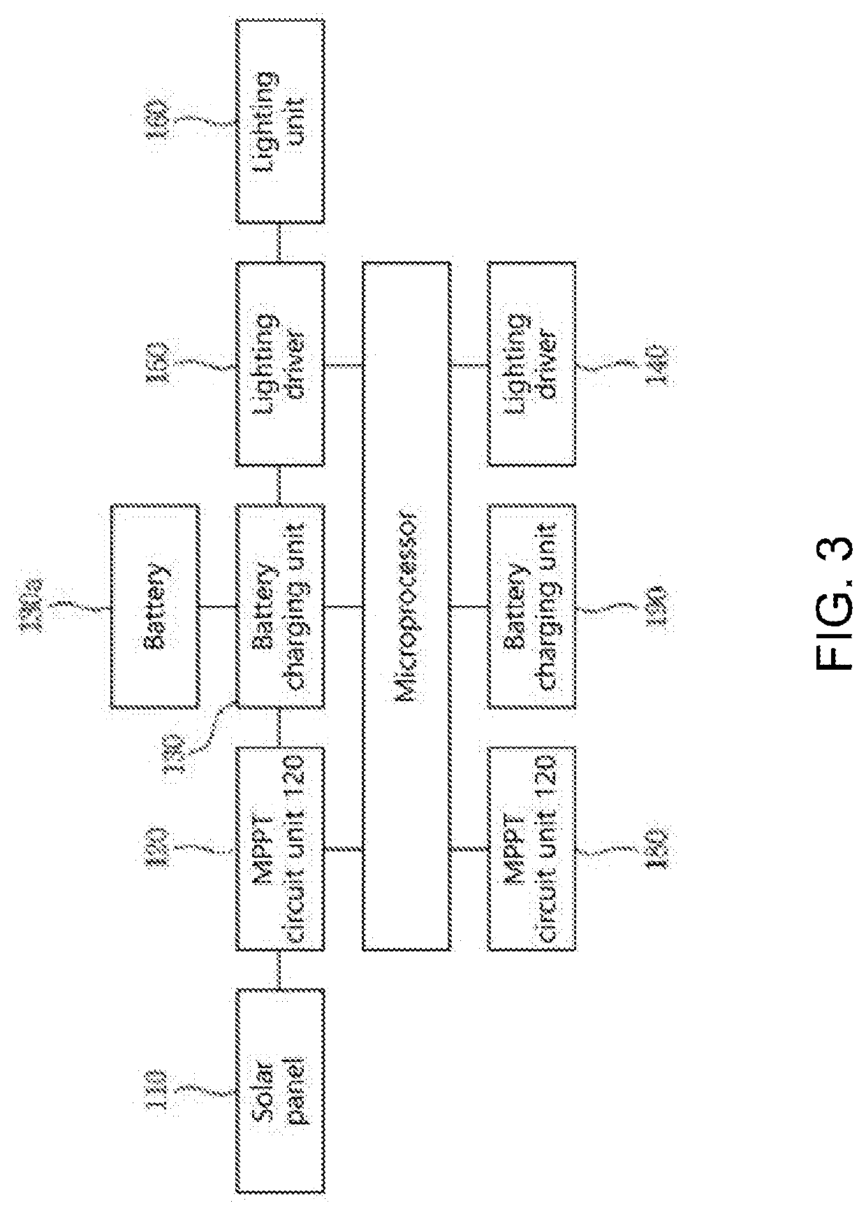
Provided in one embodiment of the present invention is a photovoltaic the lighting system comprising: an MPPT circuit unit for controlling a battery charging voltage by calculating the maximum power point of electrical energy generated from a photovoltaic panel; a battery charging unit for charging and discharging, in a battery, the electrical energy controlled by the MPPT circuit unit; a lighting unit in which a plurality of LEDs are combined; a lighting driver for turning on or off the lighting unit by supplying power supplied from the battery; and an integrated control board including a microprocessor, which checks a residual quantity of the battery, overcharging of the battery, a discharge quantity, a discharge time, and a lighting state and brightness of the lighting unit through the MPPT circuit unit, the battery charging unit, and the lighting driver so as to diagnose an error and perform integrated control.

Description

TECHNICAL FIELD[0001]The present invention relates to a solar lighting system having an integrated control board and a monitoring system using the same.BACKGROUND ART[0002]Recently, in order to handle the resource depletion of fossil fuel, power generation using natural energies, such as wind power, water power, and the sun, is actively researched.[0003]Particularly, power generation using sun energy is highly interested because the corresponding resource is abundant, an installation cost is low, and the restriction of an area is relatively small.[0004]The power generation of sun energy in which such light energy is converted into electric energy can be installed and used at places having a large amount of sunshine, such as the rooftop of a building in the downtown area and the roof of a house, without being limited to the area and topography. Power generation using such sun energy is also used a lot for power supply, such as a streetlamp, a security light, and an exit lamp.[0005]Fo...

Claims


Application Information

Patent Timeline
IPC IPC(8): H05B45/10F21S9/03H05B47/19G08C17/02F21S8/08H02J7/00H04M1/725H05B44/00
CPCG08C17/02H02J2300/26F21S8/086H02J7/0048F21S9/037H05B47/19H05B45/10H04M1/725Y02B10/10F21Y2115/10H05B47/105H02J7/35H05B45/00H05B47/115Y02B20/40F21S9/03F21W2131/103H05B47/10
Inventor PARK, DONG SIK
Owner CHORUSING
Why Eureka
Try Eureka