

Antenna apparatus, antenna module, and wireless apparatus
a technology for antenna modules and antennas, applied in the direction of polarised antenna unit combinations, instruments, and reradiation, can solve the problems of difficult configuration of array antennas on the plurality of surfaces as a single module, and achieve the effect of easy configuring of antenna modules and enlarged effective aperture portions of antennas
- Summary
- Abstract
- Description
- Claims
- Application Information
AI Technical Summary
Benefits of technology
Problems solved by technology
Method used
Image

Examples
first embodiment
Variations of First Embodiment
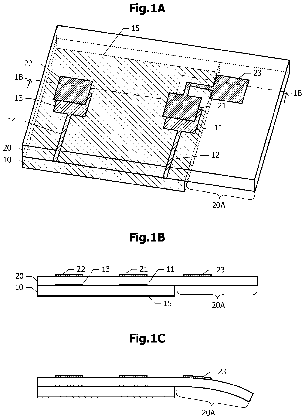
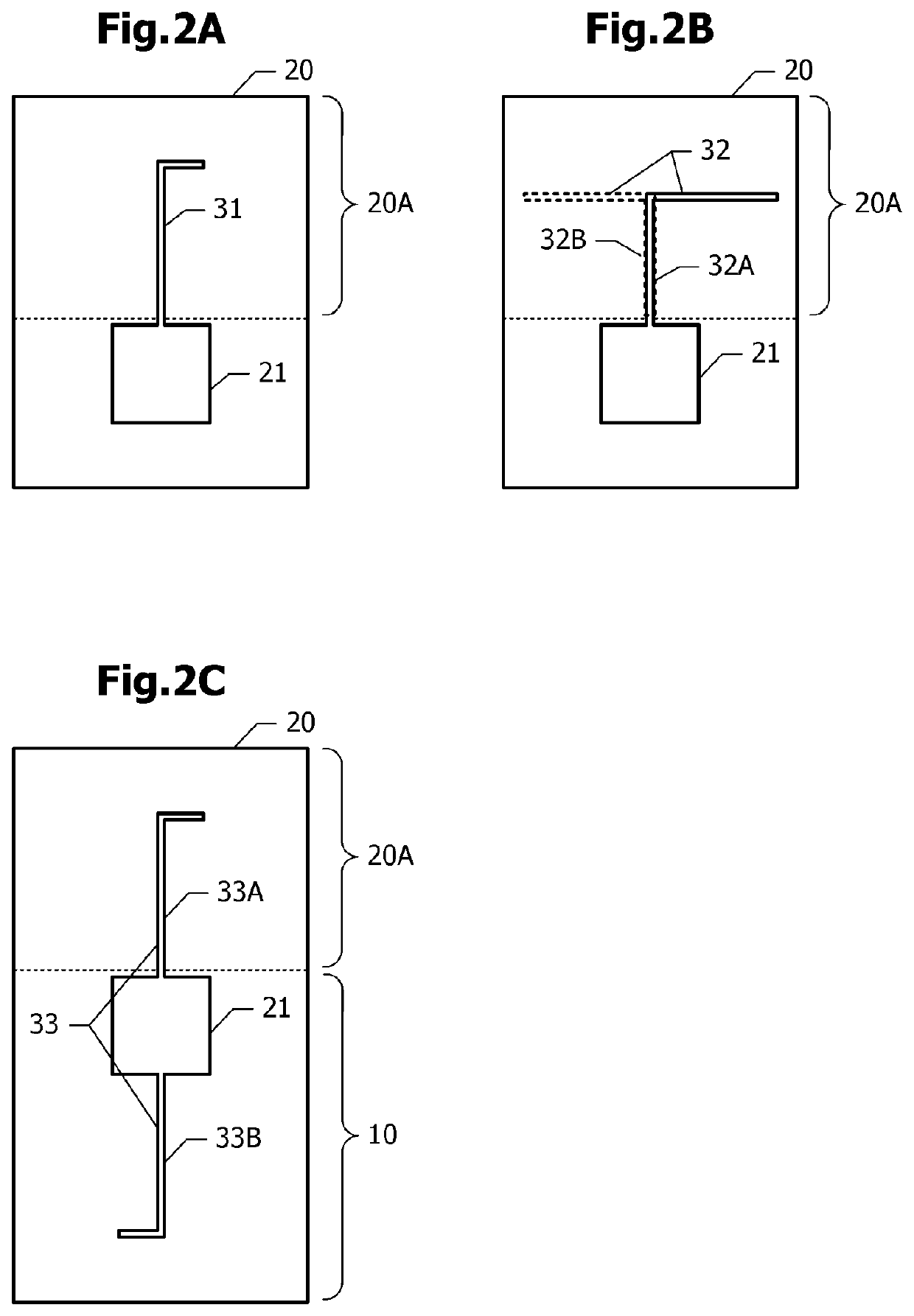
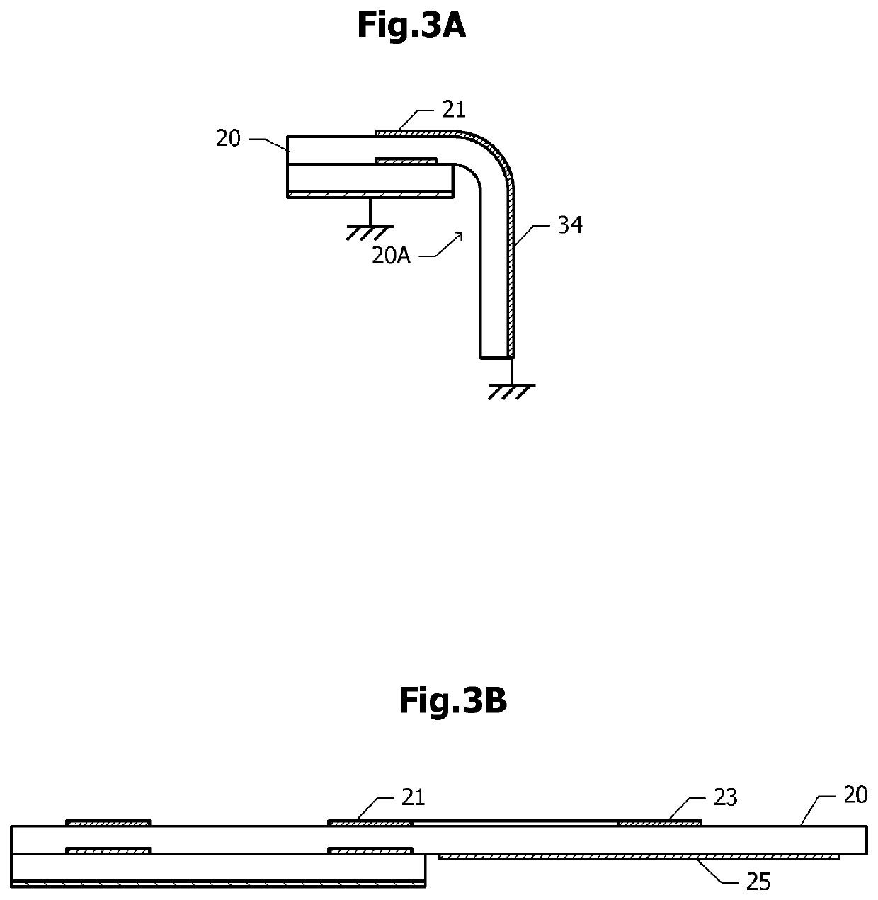
[0047]Next, antenna apparatuses according to variations of the first embodiment are described with reference to FIGS. 2A to 3B. In the first embodiment, a conductive pattern having a square or rectangular two-dimensional shape is used as one example of the radiating electrode 23. In variations described below, in place of the square or rectangular radiating electrode 23, radiating electrodes having various shapes are used. FIGS. 2A to 2C are plan views of antenna apparatuses according to variations of the first embodiment. FIGS. 3A and 3B are cross-sectional views of antenna apparatuses according to variations of the first embodiment.
[0048]In the variation illustrated in FIG. 2A, a conducting wire 31 extends from the parasitic element 21 onto the extending portion 20A of the second substrate 20. The conducting wire 31 acts as a monopole antenna.
[0049]In the variation illustrated in FIG. 2B, a L-shaped conducting wire 32A extends from the parasitic eleme...
second embodiment
[0054]Next, an antenna module according to a second embodiment is described with reference to FIGS. 4A and 4B. In the following description, the same configuration as that in the antenna apparatus according to the first embodiment (FIGS. 1A, 1B, and 1C) is not described.
[0055]FIG. 4A is a plan view of the antenna module according to the second embodiment. FIG. 4B is a cross-sectional view taken along a dash-dotted line 4B-4B in FIG. 4A. A signal line 40 is disposed on the lower surface of the second substrate 20. The signal line 40 extends from the region overlapping the first substrate 10 onto the extending portion 20A. A land 41 is disposed on an end portion of the signal line 40 adjacent to the first substrate 10. A connector 42 for connecting the antenna module to an outside circuit, such as a baseband module, is disposed on an end portion of the signal line 40 onto the extending portion 20A. As the connector 42, a connector for use in mounting on a substrate or the like may be ...
third embodiment
[0061]Next, an antenna apparatus according to a third embodiment is described with reference to FIGS. 5A and 5B. In the following description, the same configuration as that in the first embodiment illustrated in FIGS. 1A, 1B, and 1C is not described.
[0062]FIG. 5A is a plan view that illustrates a relative positional relationship between the first substrate 10 and the second substrate 20 in the antenna apparatus according to the third embodiment. In the first embodiment, the second substrate 20 extends in one direction with respect to the first substrate 10 (FIG. 1A) as seen in plan view. In the third embodiment, the second substrate 20 extends in two directions (right and left directions in FIG. 5A) with respect to the first substrate 10. Thus, the second substrate 20 includes, in addition to the extending portion 20A, an extending portion 20B.
[0063]The radiating electrode 23 connected to the parasitic element 21 is arranged on the extending portion 20A on the one side, as in the c...
PUM
 Abstract
Description
Claims
Application Information