Electrical contactor and electrical connecting apparatus

a technology of electrical contactors and electrical connections, applied in the direction of coupling device connections, instruments, measurement instrument housings, etc., can solve the problems of reducing the contact load between the electrical contactors and the electrode terminals of a testing target, and the biasing member may deteriorate, so as to achieve easy and reliable positioning

Active Publication Date: 2020-10-08
NIHON MICRONICS
View PDF0 Cites 2 Cited by
  • Summary
  • Abstract
  • Description
  • Claims
  • Application Information

AI Technical Summary

Benefits of technology

[0007]It is also desirable to improve positioning accuracy of each electrical contactor when a plurality of electrical contactors making electric contact with each of the terminals of a substrate and the electrode terminals of a testing target is attached to an electrical connecting apparatus.
[0008]Therefore, the present disclosure provides electrical contactor and an electrical connecting apparatus capable of coping with an electrical test under a high temperature environment and realizing positioning easily and reliably.
[0012]According to the present disclosure, it is possible to cope with an electrical test under a high temperature environment and realize positioning easily and reliably.

Problems solved by technology

However, in the electrical interconnect assembly having a biasing member formed of an elastomer or the like as disclosed in Patent Document the biasing member may deteriorate under a high temperature environment and a contact load between the electrical contactors and the electrode terminals of a testing target may decrease.

Method used


Image

  • Electrical contactor and electrical connecting apparatus
  • Electrical contactor and electrical connecting apparatus
  • Electrical contactor and electrical connecting apparatus

Examples


embodiment

(A) Main Embodiment

[0022]Hereinafter, an embodiment of an electrical contactor and an electrical connecting apparatus according to the present disclosure will be described in detail with reference to the drawings.

(A-1) Configuration of Embodiment

[Electrical Connecting Apparatus]

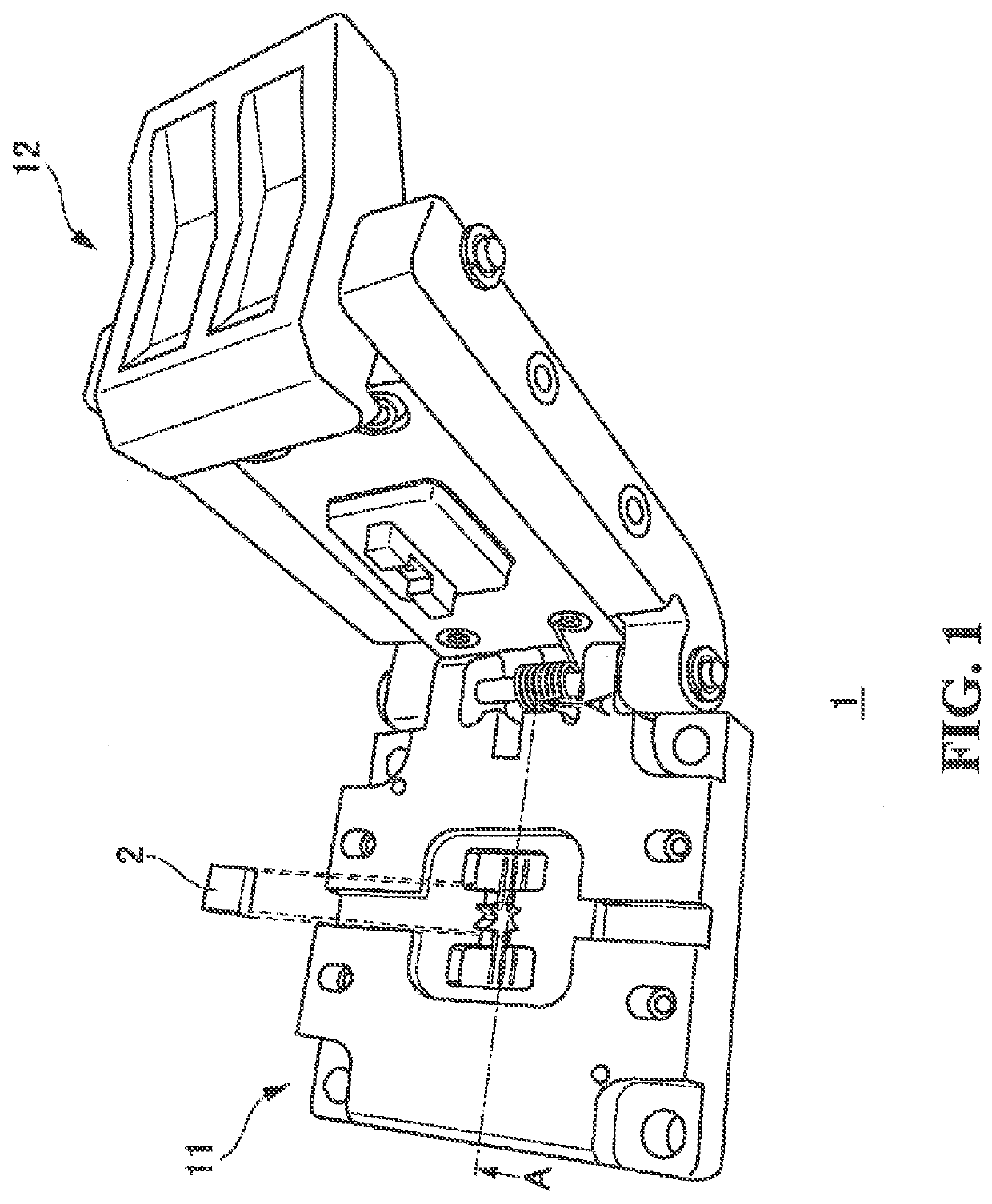
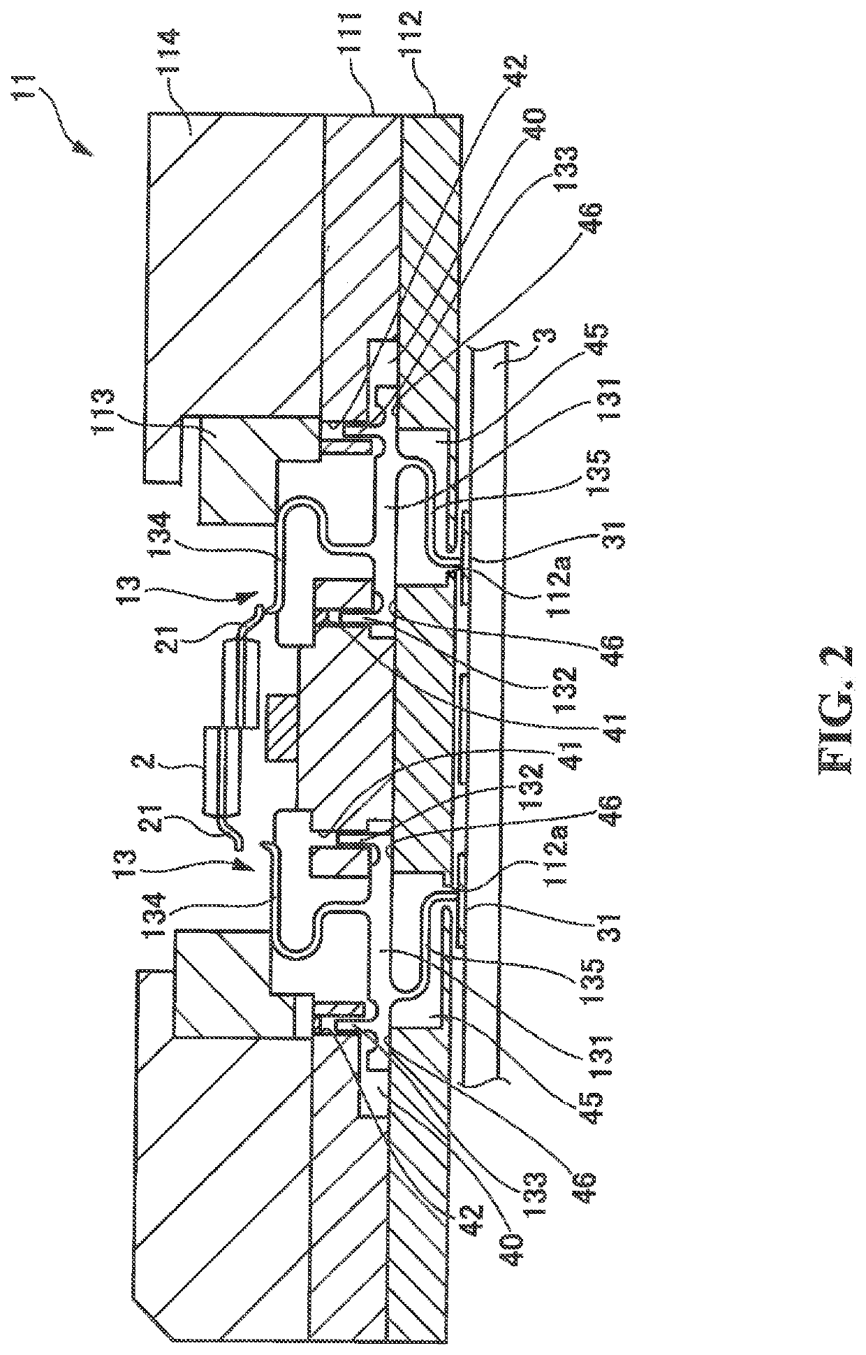
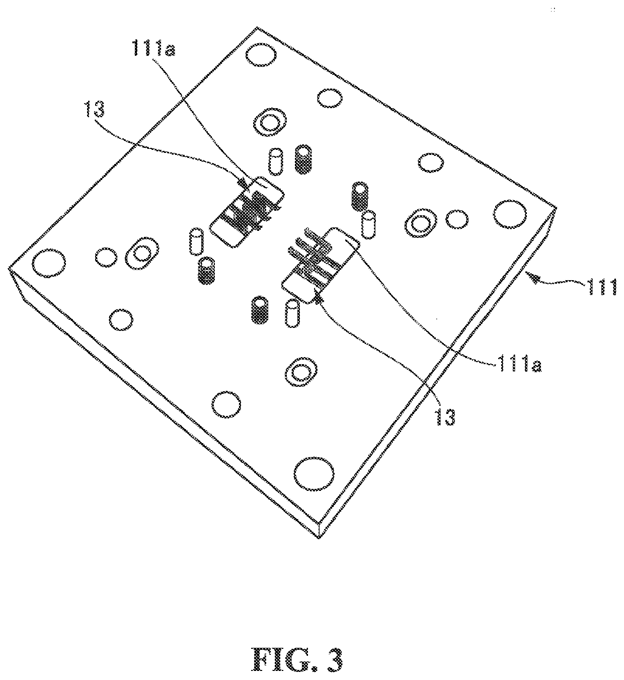
[0023]Hereinafter, a configuration of an electrical connecting apparatus will be described with reference to FIGS. 1 to 5.

[0024]FIG. 1 is a perspective view illustrating an entire configuration of an electrical connecting apparatus according to the present embodiment. FIG. 2 is a cross-sectional view along arrow A-A in FIG. 1. The left half of a testing target 2 in FIG. 2 illustrates a state in which an electrode terminal 21 of the testing target 2 is not in contact with an electrical contactor 13, and the right half of the testing target 2 illustrates a state in which the testing target 2 is pushed in so that the electrode terminal 21 of the testing target 2 is in contact with the electrical contactor 13. FI...


PUM


Abstract

An electrical contactor capable of coping with an electrical test under a high temperature environment and realizing reliable positioning is provided,An electrical contactor includes: a planar body portion formed of a conductive member; an upper arm having a cantilever beam structure, including an upper base extending integrally and continuously upward from the body Portion, an upper supporting portion extending in a horizontal direction from the upper base along the body portion, and a first distal end extending vertically upward from the upper supporting portion to make electrical contact with a first contact target; a lower arm having a cantilever beam structure, including a lower base extending integrally and continuously downward from the body portion, a lower supporting portion extending in a horizontal direction from the lower base along the body portion, and a second distal end extending vertically downward from the lower supporting portion to make electrical contact with a second contact target; a first positioning portion extending upward from one end of the body portion; and a second positioning portion extending upward from near the other end of the body portion.

Description

CROSS-REFERENCE TO RELATED APPLICATIONS[0001]The present application claims, under 35 USC 119, priority of Japanese Patent Application No. 2019-072224 filed on Apr. 4, 2019.TECHNICAL FIELD[0002]The present disclosure relates to an electrical connecting apparatus and can be applied to an electrical contactor and an electrical connecting apparatus used for a conduction test of a testing target, for example.DESCRIPTION OF RELATED ART[0003]Conventionally, in the manufacturing process of integrated circuits, an electrical characteristics test called a package test or a final test, for example, is performed on packaged integrated circuits r Such a test uses an electrical connecting apparatus (so-called a test socket) that causes an electrical contactor to make electrical contact with an electrode terminal of an integrated circuit in a state in which the integrated circuit which is a testing target is held in a state of being detachably attached state. An integrated circuit attached to the...

Claims


Application Information

Patent Timeline
Patent Type & Authority Applications(United States)
IPC IPC(8): G01R31/28H01R13/24G01R1/04
CPCG01R1/0466G01R31/2886H01R13/2442H01R13/2407G01R1/0416G01R1/0408G01R1/0458
Inventor OSATO, EICHI
Owner NIHON MICRONICS
Why Eureka
Try Eureka