
Pyrotechnic switching device

Active Publication Date: 2020-10-08
MERSEN FRANCE SB
View PDF0 Cites 1 Cited by
  • Summary
  • Abstract
  • Description
  • Claims
  • Application Information

AI Technical Summary

Benefits of technology

This patent relates to a cut-off device that uses a fuse core with an insulating shell to improve its strength and reliability. The device includes a first fuse element that is used to initiate a pyrotechnic initiator in order to switch from a first configuration to a second configuration. In the second configuration, the current can flow through the second portion of the cut-off device, which includes two conductive elements. This helps to quickly disconnect the first portion and connect the second portion, thus tripping the first fuse element and permanently cutting off the current. The use of this fuse core design also reduces the likelihood of spontaneous opening of the first fuse element, resulting in improved reliability. The cut-off device is compact and integrates the elements necessary for tripping the initiator, eliminating the need for a separate sensor. Additionally, the use of a low-rating fuse element ensures a reliable cut-off.

Problems solved by technology

However, these devices can be subject, in particular when high voltages are used in the electrical circuit, to the formation of electric arcs.
These electric arcs increase the time required to cut off the current in the circuit and generally reduce the reliability of the cut-off device.
After the initiator is tripped and the conductive bar is broken, all the current passes through the fuse, causing it to melt, and permanently cuts off the current in the circuit.
This type of device generally operates effectively but, over time, the fuse can be subject to aging, which can ultimately affect its reliability.

Method used


Image

  • Pyrotechnic switching device
  • Pyrotechnic switching device
  • Pyrotechnic switching device

Examples


Embodiment Construction

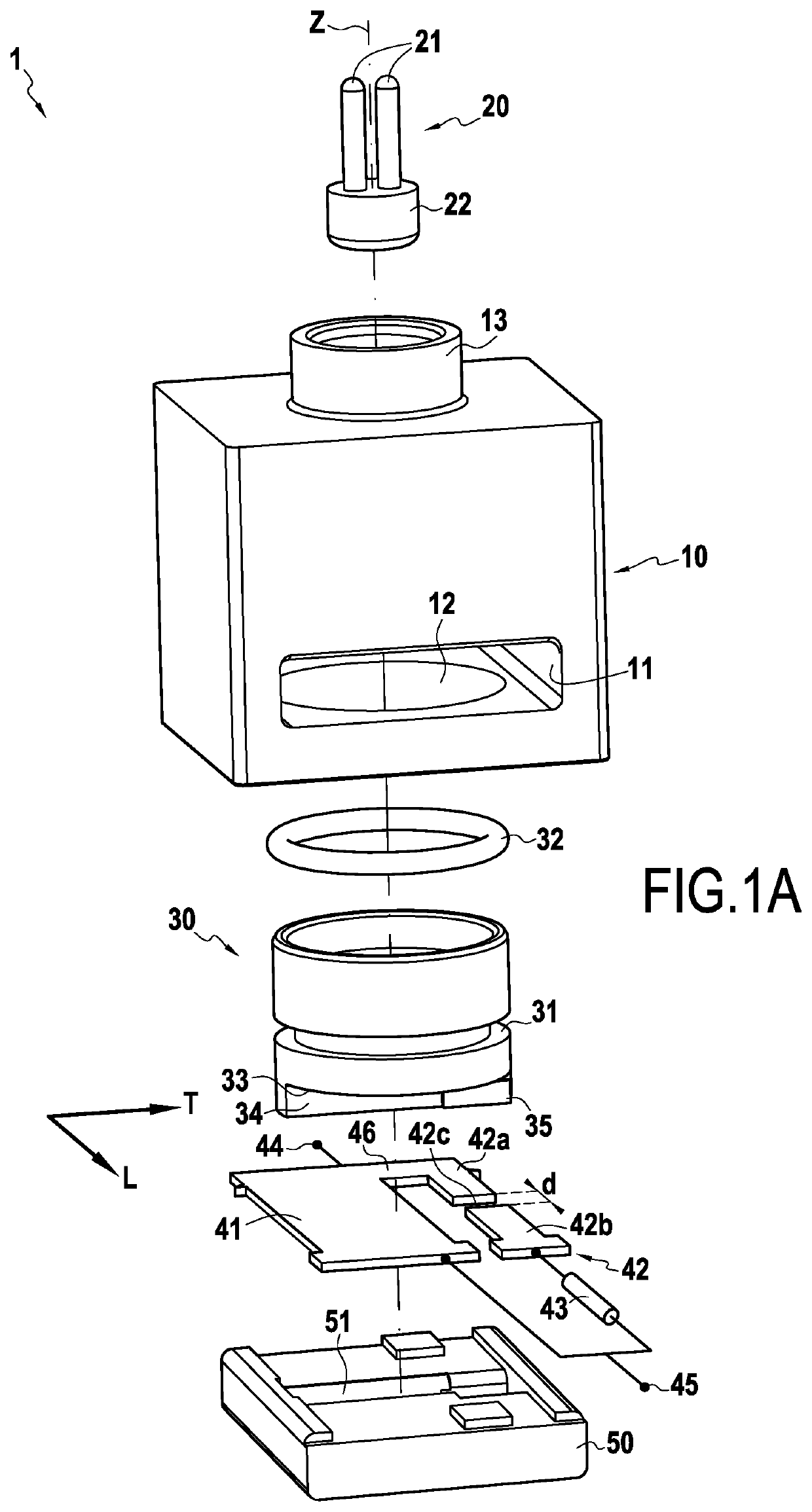
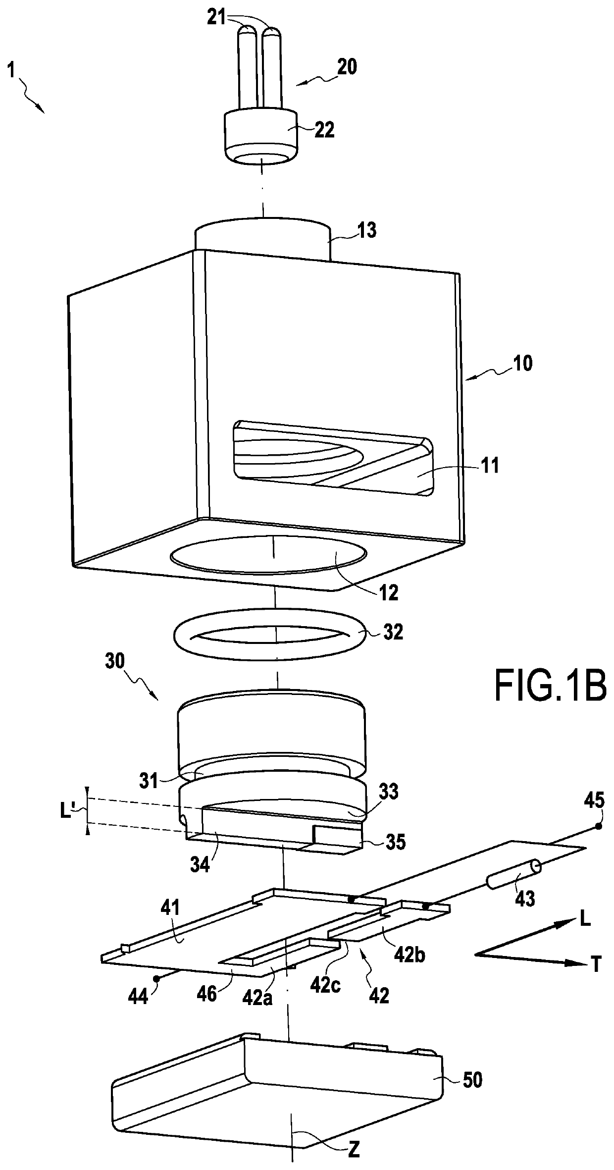
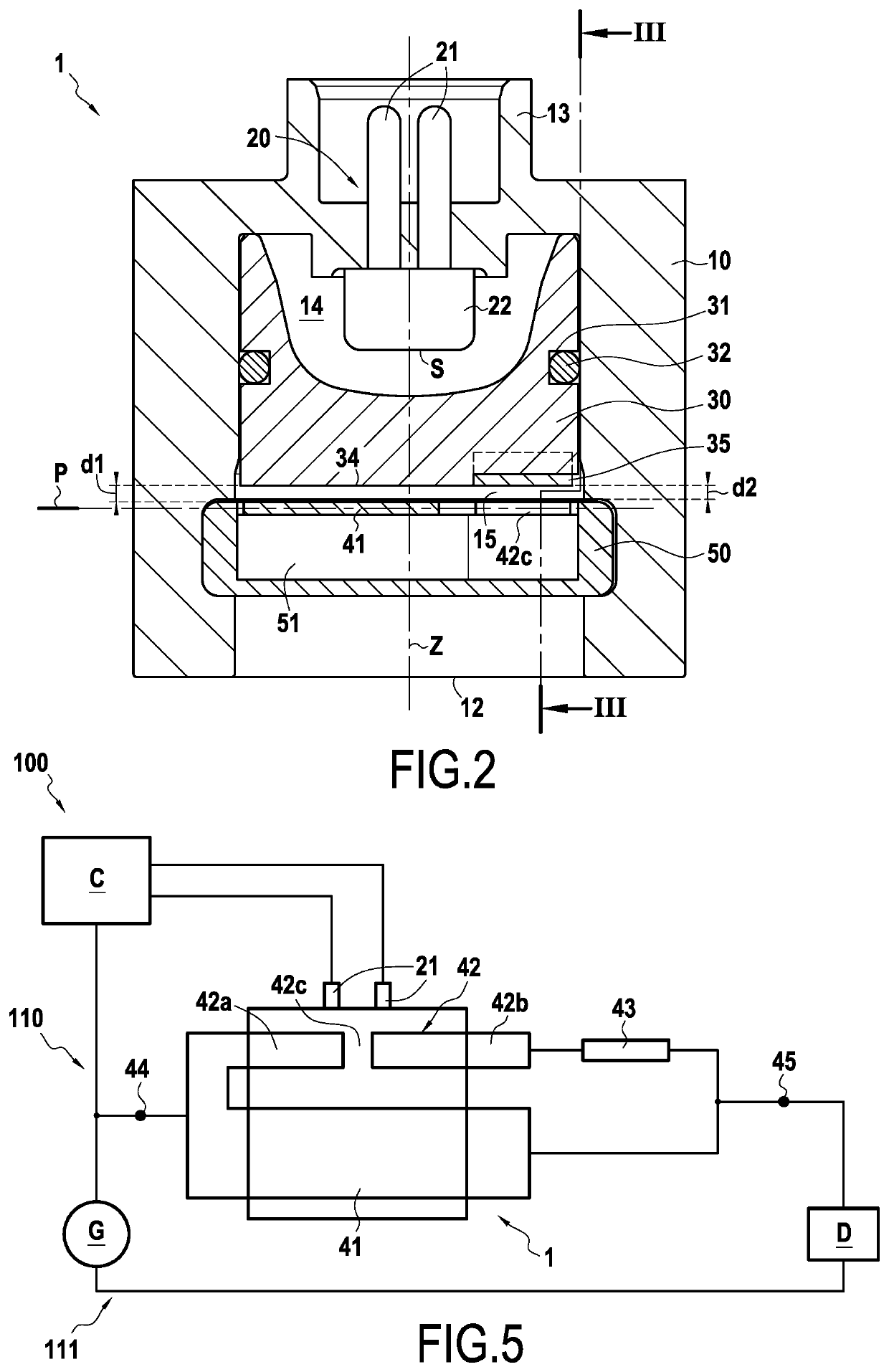
[0043]FIGS. 1A and 1B show two exploded views of a cut-off device 1 according to one embodiment of the invention. The illustrated cut-off device 1 comprises: a body 10, a pyrotechnic initiator 20, a piston 30, a first conductive portion 41, a second portion 42, a first fuse element 43 and a support 50. In the illustrated example, the longitudinal direction L corresponds to the direction along which the portions 41 and 42 extend and connecting the terminals 44 and 45 of the device 1. The transverse direction T is perpendicular to this direction L in the plane of the portions 41 and 42.

[0044]The device 1 comprises a first 44 and a second 45 electrical terminal which are intended to be connected to an electrical circuit to be cut off. The first conductive portion 41 and the second portion 42 are mounted in parallel with each other between the first terminal 44 and the second terminal 45 of the cut-off device. The first conductive portion 41 electrically connects the first terminal 44 t...


PUM


Abstract

A pyrotechnic cut-off device to be connected to an electrical circuit to cut-off, includes a pyrotechnic initiator, a first and a second conductive portion each intended to be connected to the electrical circuit, the second portion being connected in parallel with the first portion and including two conductive elements separated by an insulating segment, at least one of the conductive elements provided with a first fuse element connected in series which is configured to trip when the intensity of the current passing therethrough exceeds a first predetermined value, and a first and a second insulating protrusion, each protruding from a lower face of a movable piston and the first and the second protrusions being located respectively in front of the first portion and the insulating segment. The pyrotechnic initiator is configured to switch the cut-off device from a first current passage configuration to a second current cut-off configuration.

Description

BACKGROUND OF THE INVENTION[0001]The present invention relates to the general field of electrical cut-off devices, and more particularly those of the pyrotechnic actuation type. The invention also relates to an electrical system secured by such a device.[0002]There are known pyrotechnic cut-off devices comprising a body in which a pyrotechnic initiator is present configured, when tripped, to set a piston in motion provided with a protrusion in the direction of a conductive bar to be cut. Documents WO 2016 / 038043 and WO 2016 / 038050 show examples of devices of this type. However, these devices can be subject, in particular when high voltages are used in the electrical circuit, to the formation of electric arcs. These electric arcs increase the time required to cut off the current in the circuit and generally reduce the reliability of the cut-off device.[0003]To overcome the occurrence of these arcs, a fuse can be connected in parallel with the conductive bar of such devices. When the ...

Claims


Application Information

Patent Timeline
IPC IPC(8): H01H85/02H01H39/00
CPCH01H39/006H01H85/0241H01H39/004
Inventor MATHIEU, ALEXANDRELORENZON, ROMAINDE PALMA, JEAN-FRANÇOISOUAIDA, RÉMY
Owner MERSEN FRANCE SB
Learn More