Flow-cooled toroidal or circular power electronics

Active Publication Date: 2020-10-15
INST FR DU PETROLE
View PDF5 Cites 0 Cited by
  • Summary
  • Abstract
  • Description
  • Claims
  • Application Information

AI Technical Summary

Benefits of technology

The invention aims to cool power electronic systems efficiently and design them in a simple way. It intends to minimize the costs associated with wiring between electronic components and the electric machine. Additionally, it aims to reduce the usage of materials for power components. The technical effect of the patent is to provide a cooling solution that is effective while incorporating electronic components as close as possible to the electric machine.

Problems solved by technology

The heat generated may bring the power components to temperatures that are such that the performance of the power components may be negatively affected, and their structures may even be damaged.
This is especially so in thermally restrictive environments, such as is the case for an internal combustion engine.
The prior art has drawbacks such as, in particular, the need for cooling systems that are difficult to design and to incorporate, such as water cooling circuits or fans, or such as the need to use power components which withstand high temperatures well when they are arranged in proximity to an internal combustion engine.
This entails extra cost for the power electronic systems.

Method used


Image

  • Flow-cooled toroidal or circular power electronics
  • Flow-cooled toroidal or circular power electronics
  • Flow-cooled toroidal or circular power electronics

Examples


Embodiment Construction

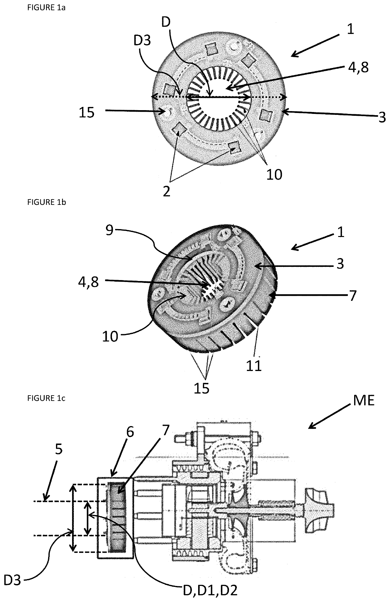
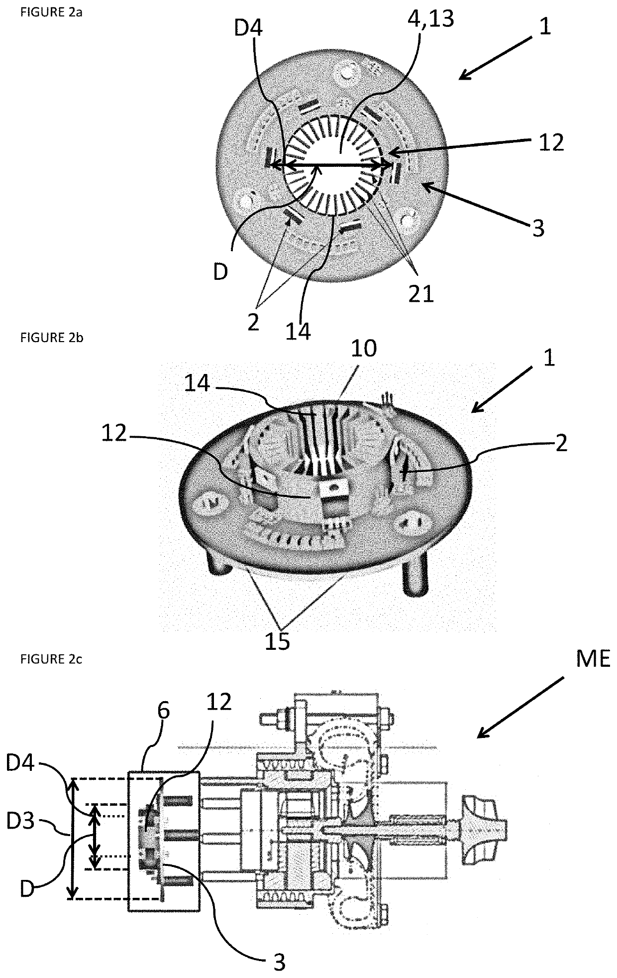
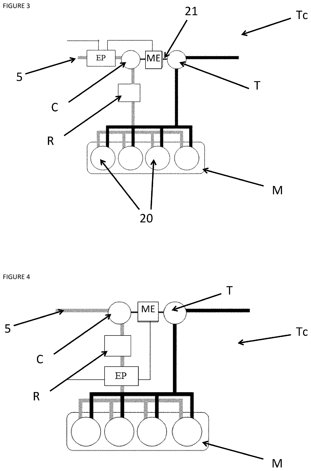
[0046]The invention is power electronics (1) for powering electric machines (ME) which are located in powertrains comprising a motor or engine (M), in particular an internal combustion engine. The electric machines (ME) may be used for example for supercharging internal combustion engines and may be, without limitation, compressors (C) or turbochargers (Tc) driven by an electric machine. These power electronics (1) may comprise one or more circuit boards (3), on which electronic components are mounted. In the case that the power electronic system (1) is an inverter, serving to interface a current source with an electric machine (ME). The power electronic system (1) may comprise power electronic components (2). These power electronic components (2) are incorporated on one of the circuit boards (3). The circuit boards (3) may be incorporated within a mechanical housing (6). In the context of the invention, the power electronic components (2) are cooled by a flow which circulates throu...


PUM


Abstract

The invention is a power electronic system comprising at least one power electronic component implemented at least partly on at least one circuit board. The circuit boards are planar and circular or toroidal in shape with the center thereof comprising a circular opening having a diameter D cooperating with a hose for circulating a flow.

Description

CROSS-REFERENCE TO RELATED APPLICATIONS[0001]Reference is made to International Application No. PCT / EP2018 / 082883, filed Nov. 28, 2018, which claims priority to French Patent Application No. 17 / 62.370, filed Dec. 18, 2017, the contents of which are incorporated herein by reference in their entirety.BACKGROUND OF THE INVENTIONField of the Invention[0002]The present invention relates to the field of power electronic systems, in particular for controlling electric machines such as, in particular, supercharger systems used for example for internal combustion engines. More specifically, the invention relates to a power electronic system that is configured to be cooled by a cooling device.Description of the Prior Art[0003]Certain power electronic systems may be DC-to-AC power electronic converters, in particular inverters, which interface DC voltage sources with AC electric machines. These inverters perform functions that are essential for electrical conversion and shape electrical quanti...

Claims


Application Information

Patent Timeline
IPC IPC(8): H05K7/20H05K1/02F02B33/40
CPCH05K1/0203H05K7/209H05K7/20172H05K7/20327F02B33/40H05K7/20927H05K7/20909H05K7/20918H02K11/33
Inventor BATTISTON, ALEXANDREKEFSI, LAIDLE BERR, FABRICE
Owner INST FR DU PETROLE
Why Eureka
Try Eureka