Transmission device, transmission method, reception device, and reception method

Inactive Publication Date: 2020-10-22
SATURN LICENSING LLC
View PDF0 Cites 3 Cited by
  • Summary
  • Abstract
  • Description
  • Claims
  • Application Information

AI Technical Summary

Benefits of technology

This patent discusses the issue of providing high-quality moving images at a high frame rate, which can cause image quality issues when displayed on a receiver that operates at a lower frame rate. The patent proposes a solution that converts the moving image data captured by a camera with a high-speed frame shutter into a sequence of smaller images and displays them at a lower frame rate. This technology aims to improve image quality while reducing costs associated with heavy-load calculations required for improved motion vector search accuracy.

Problems solved by technology

However, while images captured with the high-speed frame shutter produce advantageous effects of improving motion blurs and achieving high quality with high sharpness, these images have such an aspect that a problem of image quality may be caused in a conventional frame interpolation technology on the receiving and reproducing side which displays a sequence of moving image at a frame rate lower than a distributed high frame rate.
Heavy-load calculation which is required for improving accuracy of motion vector search during frame interpolation influences costs of the receiver.

Method used


Image

  • Transmission device, transmission method, reception device, and reception method
  • Transmission device, transmission method, reception device, and reception method
  • Transmission device, transmission method, reception device, and reception method

Examples


first embodiment

1. First Embodiment

[Transmission and Reception System]

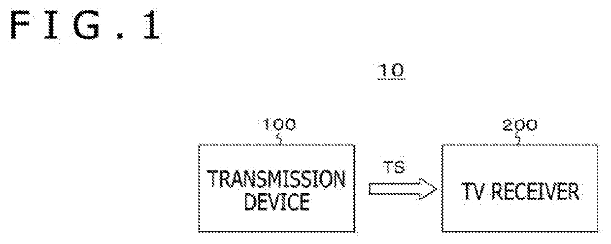
[0058]FIG. 1 depicts a configuration example of a transmission and reception system 10 according to a first embodiment. The transmission and reception system 10 includes a transmission device 100 and a TV receiver 200.

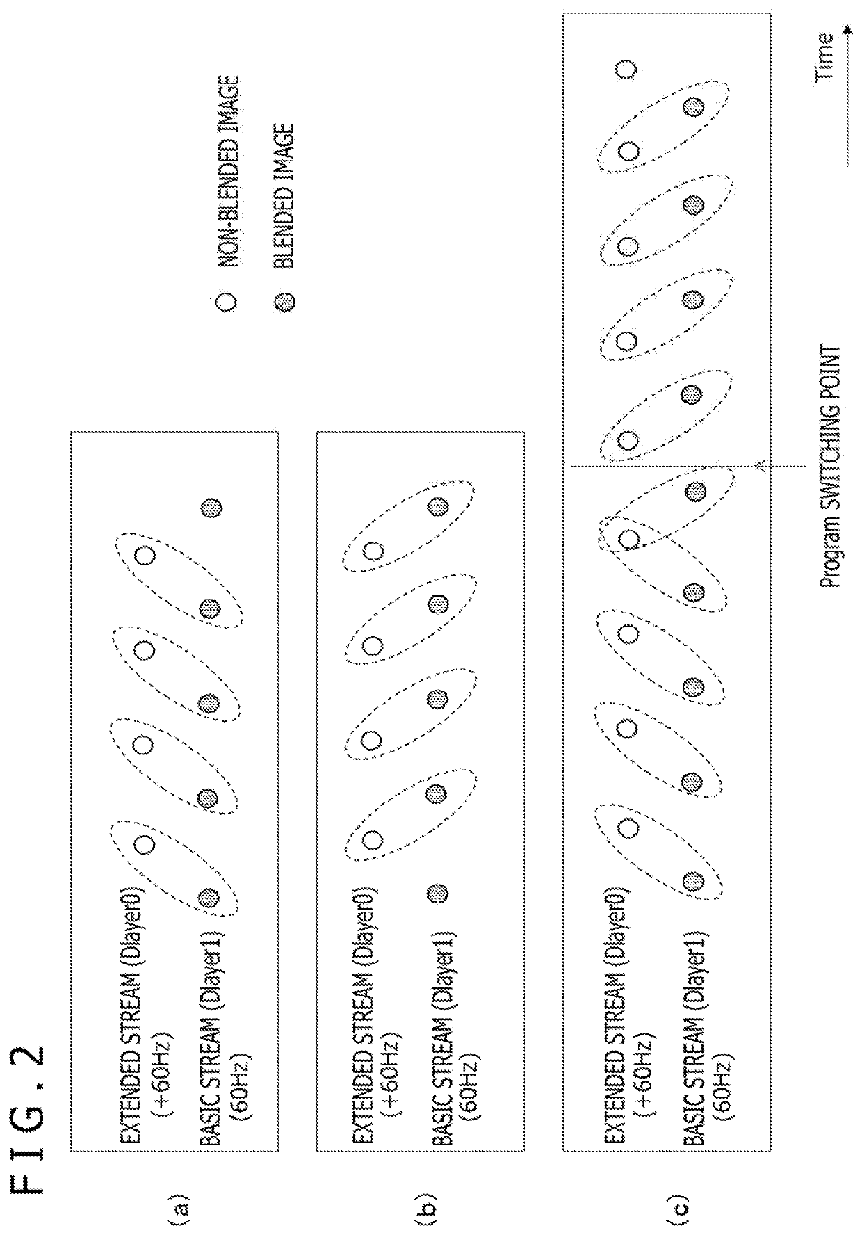
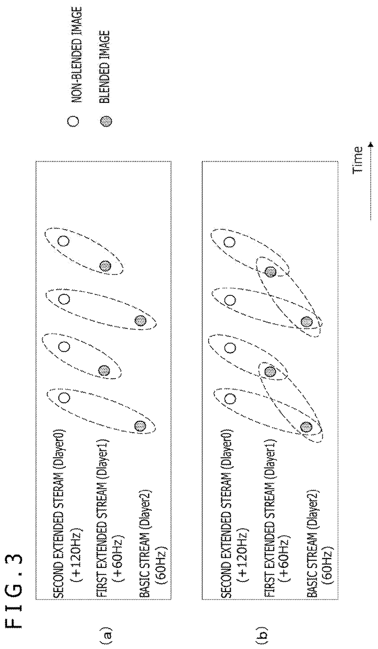
[0059]The transmission device 100 transmits a transport stream TS functioning as a container and carried on a broadcast wave. The transport stream TS includes a basic stream (basic video stream) and a predetermined number of extended streams (extended video streams) obtained by processing moving image data at a high frame rate, or 120 Hz or 240 Hz in this embodiment. According to this embodiment, each of the basic stream and the extended streams has an NAL unit structure.

[0060]The basic stream herein is obtained in the following manner. More specifically, blended moving image data at the high frame rate is obtained by performing a blending process for blending image data indicating respective pictures of moving imag...

second embodiment

2. Second Embodiment

[Transmission and Reception System]

[0198]While the example of the transmission and reception system 10 constituted by the transmission device 100 and the TV receiver 200 has been described in the above embodiment, the configuration of the transmission and reception system to which the present technology is applicable is not limited to this example. Also considered is such a configuration that the part of the TV receiver 200 is constituted by a set top box and a display connected via a digital interface, such as HDMI (High-Definition Multimedia Interface). Note that “HDMI” is a registered trademark.

[0199]FIG. 20 depicts a configuration example of a transmission and reception system 10A according to a second embodiment. The transmission and reception system 10A includes the transmission device 100, a set top box (STB) 200-1, and a display 200-2. The set top box (STB) 200-1 and the display 200-2 are connected to each other via HDMI. Note that the digital interface c...


PUM


Abstract

An inverse blending process is appropriately and easily performed on a receiving side in a case of transmission of blended moving image data.Information indicating blending rates and information indicating blending target pictures are inserted into encoded image data associated with pictures of blended images in a case of transmission of blended moving image data. In addition, information indicating blending rates and information indicating blending target pictures in correspondence with image data associated with pictures of blended images are also transmitted in a case of transmission of blended moving image data by a digital interface. An inverse blending process can be appropriately and easily performed on a receiving side on the basis of the information indicating the blending rates and the information indicating the blending target pictures.

Description

TECHNICAL FIELD[0001]The present technology relates to a transmission device, a transmission method, a reception device, and a reception method, and more particularly to a transmission device and others for transmitting blended moving image data.BACKGROUND ART[0002]A camera which performs imaging at a high frame rate using a high-speed frame shutter is known in recent years. For example, a normal frame rate is 60 Hz or 50 Hz, while a high frame rate is a frame rate several times or several tens of times, or further several hundreds of times the normal frame rate.[0003]It is considered that a service at a high frame rate can be provided by converting moving image data captured by a camera with a high-speed frame shutter into a sequence of moving images at a frequency lower than that of the high frame rate, and transmitting the converted moving image data. However, while images captured with the high-speed frame shutter produce advantageous effects of improving motion blurs and achiev...

Claims


Application Information

Patent Timeline
IPC IPC(8): H04N21/234H04N21/2365H04N21/44G06T3/40G06T9/00H04L29/06
CPCG06T9/00H04L65/607H04L65/601G06T3/4038H04N21/2365H04N21/44H04N21/234H04N19/172H04N19/31H04N19/587H04N19/70H04N19/85H04N21/2343H04N21/2362H04N19/132H04N21/234381H04L65/70H04L65/75
Inventor TSUKAGOSHI, IKUO
Owner SATURN LICENSING LLC
Why Eureka
Try Eureka