Tracheal intubation facilitator with superior ventilating capability, with a system to accurately place endobronchial tubes in the desired bronchus

Pending Publication Date: 2020-10-29
ANANTHANARAYANAN KALYANARAMAN +2
View PDF0 Cites 1 Cited by
  • Summary
  • Abstract
  • Description
  • Claims
  • Application Information

AI Technical Summary

Benefits of technology

The patent text is about a device called a bougie that is used to help insert a breathing tube into a person's airway. The text explains that the bougie will be marked with numbers to show how far it has gone into the airway. This helps the physician know how far the breathing tube is from the person's mouth. The technical effect of this is that it provides a more accurate way to insert the breathing tube and ensure that it is positioned correctly in the airway.

Problems solved by technology

It is necessary that the assisted ventilation of a patient under anaesthesia or respiratory distress is initiated with a minimal time lag as lack of oxygen supply for a few minutes can be fatal for most patients.
Also, ‘securing’ the airway in unconscious patients is essential to prevent the patients stomach contents getting aspirated into the lungs resulting in a life threatening complication ‘aspiration pneumonitis’.
But as many as 5-10% of the patients requiring emergency intubation have various associated airway abnormalities which makes the intubation difficult.
Difficulty in intubation is commonly associated with obesity, pregnancy, facial trauma / abnormalities, short thick neck, laryngeal edema etc.
When such an abnormality is associated with decreased respiratory reserve, routine intubation procedures may become difficult or even risky, leading to desaturation and cardiac arrest.
But in 5-10% of patients, vocal cords are not visualised or incompletely visualised due to their anterior placement, making it difficult or impossible to intubate with a normal tracheal tube.
During bougie guided intubation the passage of ETT over the bougie into the trachea may take a considerable time and may often requires multiple attempts, during which the patients will exhaust his oxygen reserves and often the bougie needs to be removed and the patient ventilated with face mask.
1) The risk associated with mask ventilation like pulmonary aspiration of gastric contents (a life threatening condition).
2) Risk associated with repeated laryngoscopy attempts, like oral trauma, breakage of teeth, myocardial ischaemia in coronary artery disease, increased trauma to airways or vocal cords or increased airway edema.
3) Risks associated with desaturation like cardiac arrest or permanent brain damage.
Also during intubation, the available “ventilating bougie's are not capable of providing effective ventilation of the lungs because most of the air is lost through the nasal and oral routes as they are the path of least resistance instead of going to the lungs.
Hence chances of hypoxia increase.
Additionally, another problem with the previously known bougies is the lack of confirmation of the tracheal placement of the distal end of the bougie.
If the ETT is mistakenly placed in the patient's oesophagus, subsequent ventilation may be ineffective, leading to asphyxiation.
As these bougies'” (which are available in the market) tip are bent hence angle of curvature cannot be changed during the laryngoscopy therefore if the bent bougie tip does not enter inside the laryngeal cavity, it has to be removed and bent at a more appropriate angle for reinsertion, resulting in multiple attempts, which increases apnoea time and causes hypoxia, resulting into haemodynamic disturbances.
In these situations, confirmation of proper placement of the bronchial tube is difficult and is often achieved by auscultation / bronchoscopy.
This results in multiple attempts.

Method used


Image

  • Tracheal intubation facilitator with superior ventilating capability, with a system to accurately place endobronchial tubes in the desired bronchus
  • Tracheal intubation facilitator with superior ventilating capability, with a system to accurately place endobronchial tubes in the desired bronchus
  • Tracheal intubation facilitator with superior ventilating capability, with a system to accurately place endobronchial tubes in the desired bronchus

Examples


Embodiment Construction

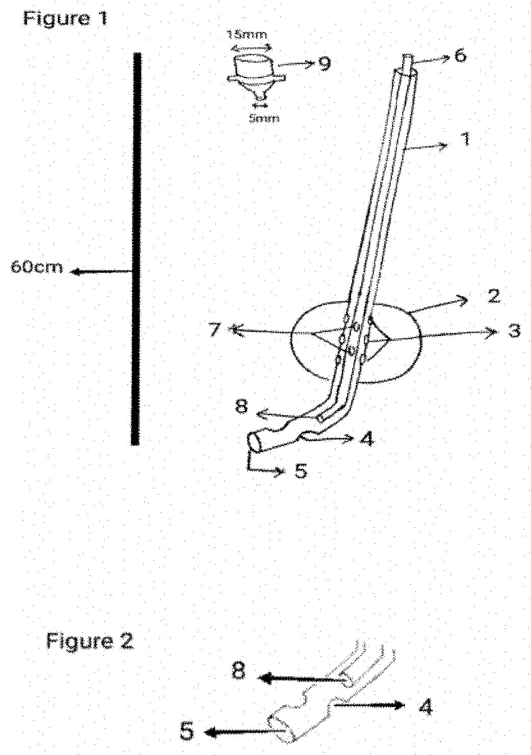
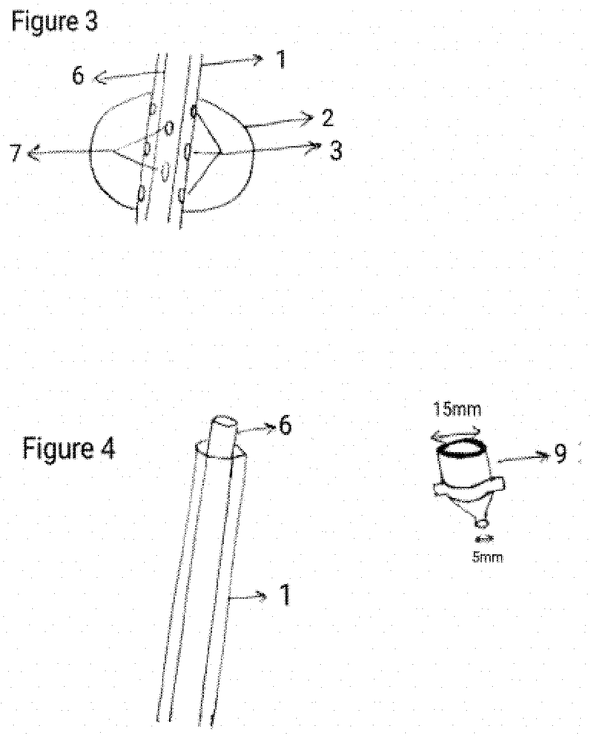
[0038]FIG. 1 is a longitudinal section of the Tracheal Tube Insertion Facilitator (‘modified bougie’). It shows the different component of the apparatus which consists of body (1), dynamic inflatable cuff (2), bougie inflation ports (3), bougie ventilation ports (4), distal bougie tip (5), hollow stylet (6), dual purpose stylet inflation / ventilation ports (7), stylet distal tip (8), universal connector (9).

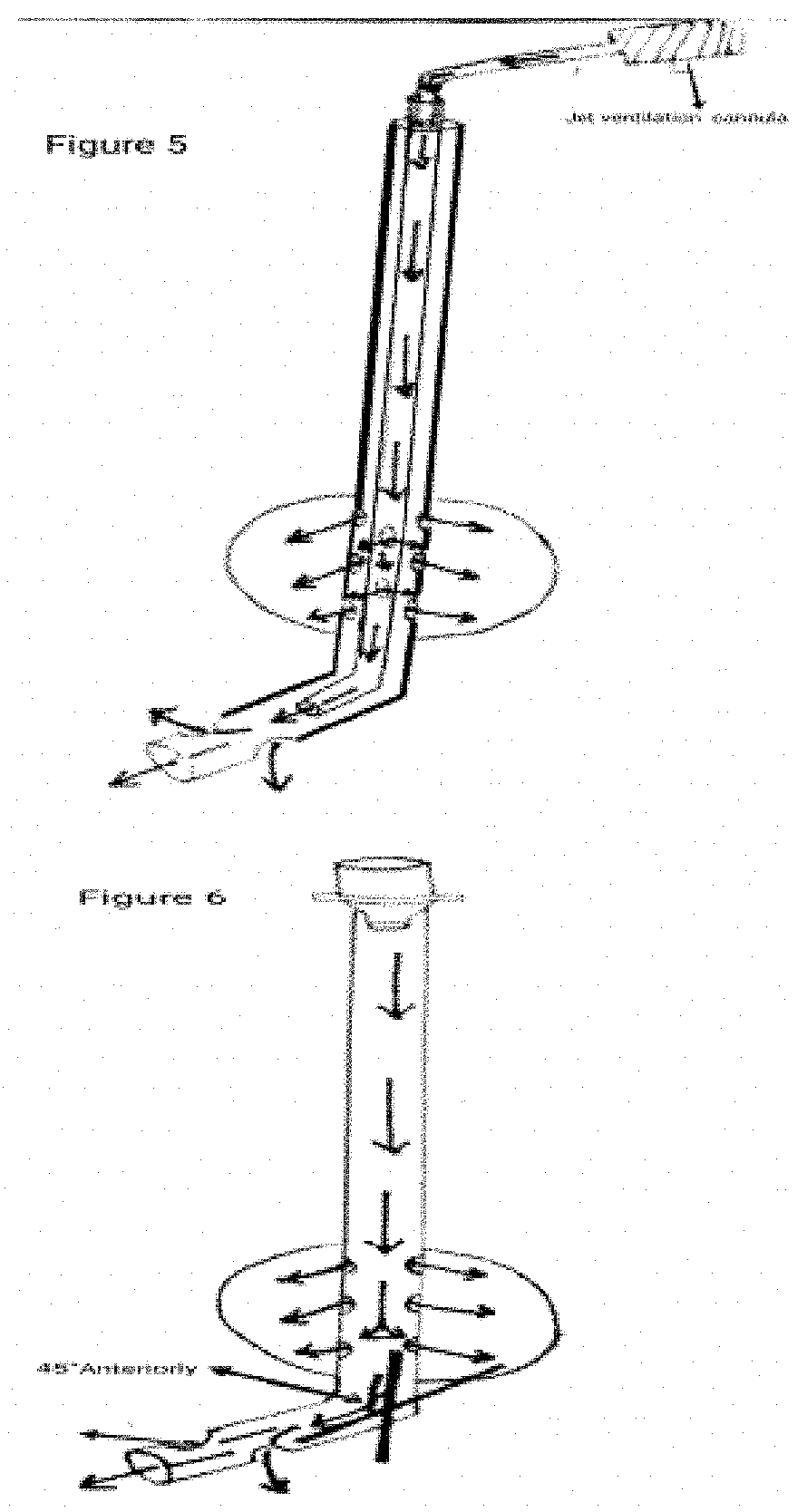
Further diagrams explain each component of the Bougie in detail.

[0039]FIG. 2 shows the bougie's ventilation ports (4), distal tip of the bougie (5), distal tip of the stylet (8). The two ventilation ports (4) lies on the lateral aspects of the bougie, in between the distal tip and the dynamic cuff and are in connection with the bougie lumen for the purpose of ventilation. The distal bougie tip (5), is bent forward with an angle of about 45 degrees. The stylet's distal tip (8) helps in ventilation during dire emergency situations where stylet can directly be attached to a jet venti...


PUM


Abstract

We describe a Tracheal Tube insertion facilitator (“modified bougie”) with superior ventilating capability to enable medical / paramedical personnel to place tracheal / bronchial tubes reliably in trachea / bronchus of the patients under anaesthesia or patients in respiratory distress, and provide respiratory support. This device is particularly useful in situations where the conventional tracheal intubation technique using a laryngoscope is difficult or near impossible. This device has a outer cylindrical member, inner hollow stylet and a dynamic cuff which inflates during Positive Pressure Ventilation / Jet ventilation, and hence enabling oxygenation in patients with respiratory distress even before the tracheal tube is inserted into the patient's airway.

Description

FIELD OF INVENTION[0001]The present invention discloses a medical airway device, more specifically a modified Tracheal Tube Insertion Facilitator (“modified Bougie”) with superior ventilating capability to aid the placement of tracheal / bronchial tubes in the airway of patients, particularly the ones which are difficult with conventional laryngoscopy aided intubation technique. This device is characterized by a outer cylindrical member, a dynamic cuff which inflates with Positive Pressure Ventilation (PPV), a ventilating stylet, a flexible tip, and a colour coded and calibrated body which is suitable for facilitating insertion of an endotracheal / endobronchial tube into the airway of a person while simultaneously providing effective ventilation to the lungs.BACKGROUND AND PRIOR ART OF INVENTION[0002]This device has its application in patients who are unconscious or under general anaesthesia, who have inadequate or absent respiratory efforts. In emergency medical management of a patien...

Claims


Application Information

Patent Timeline
IPC IPC(8): A61M16/04A61M25/01
CPCA61M25/0102A61M2205/6081A61M16/0488A61M2210/1032A61M2210/105A61M2210/1035A61B1/2676A61M16/0434A61M2205/6063A61M16/044A61M16/0411A61M16/0452A61M2205/584A61M16/0418
Inventor ANANTHANARAYANAN, KALYANARAMANPATYAL, ASHISHKOTAK, NIRAV
Owner ANANTHANARAYANAN KALYANARAMAN
Why Eureka
Try Eureka