Electrosurgical Pericardial Puncture

a technology of pericardial puncture and electrosurgical technique, which is applied in the field of electrosurgical pericardial puncture, can solve the problems of laceration of the myocardium, increased risk, and associated risks, and achieve the effect of reducing the risk of damaging the myocardium layer

Pending Publication Date: 2020-11-12
BAYLIS MEDICAL
View PDF0 Cites 1 Cited by
  • Summary
  • Abstract
  • Description
  • Claims
  • Application Information

AI Technical Summary

Benefits of technology

[0007]The problem of accessing the pericardial cavity while reducing the risk of damaging the myocardium layer is solved by a method comprising the steps of: (a) advancing a puncture device towards a heart, the puncture device including an energy delivery device at a distal end of the puncture device; (b) delivering a single pulse of a pulsed energy through the energy delivery device to a parietal pericardium of the heart to create a void relatively close to the energy delivery device while maintaining the distal end of the puncture device in a substantially stationary position relative to the parietal pericardium; (c) advancing the puncture device a short dis

Problems solved by technology

This technique, however, has various risks associated with it, the most notable of which is the laceration of the myocardium by the needle.
This risk is heightened in cases where the pericardial cavi

Method used


Image

  • Electrosurgical Pericardial Puncture
  • Electrosurgical Pericardial Puncture
  • Electrosurgical Pericardial Puncture

Examples


Embodiment Construction

[0026]To gain access to the pericardial cavity for performing treatment procedures, such as catheter mapping and ablation, prior art devices typically comprise needles or other traumatic puncturing members that may cause damage to the myocardium when advanced towards the heart.

[0027]The present inventors have discovered a method which provides for safely accessing the pericardial cavity of the heart of a human or animal while minimizing the risk to the heart wall. Various embodiments of the method avoid the use of rigid piercing members and the associated risks.

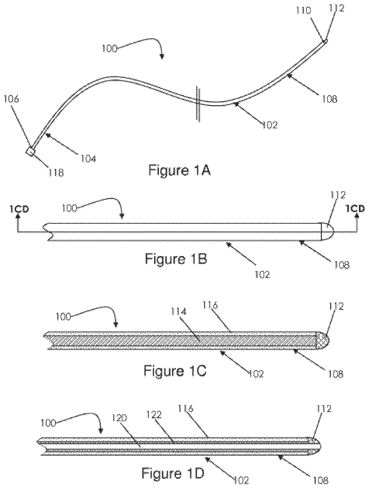
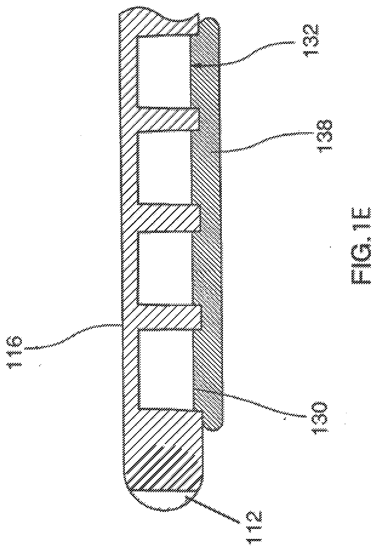
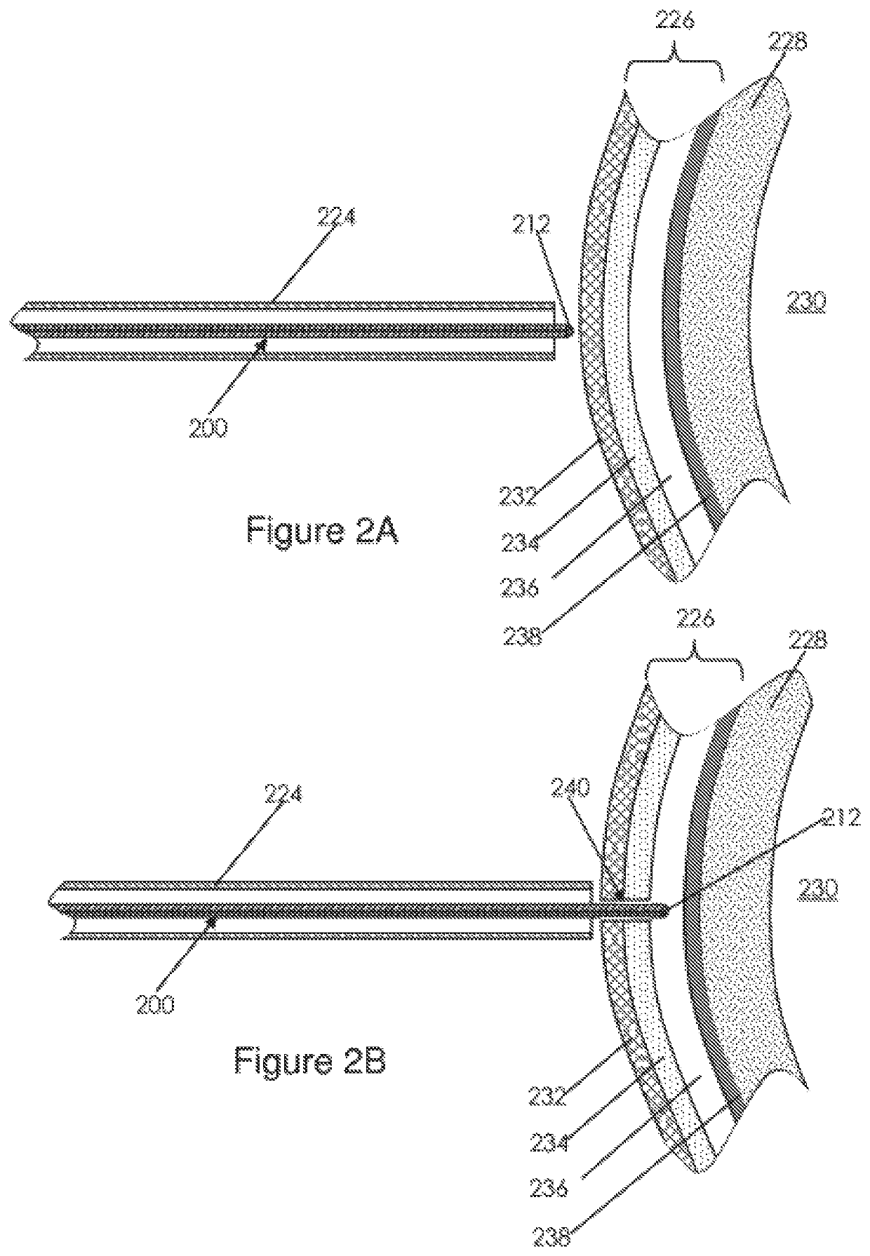
[0028]The method includes advancing a puncture device towards the heart of a patient. The distal end of the puncture device is atraumatic and comprises an energy delivery device. The energy delivery device is positioned at a target site on a pericardium of the heart and energy is delivered from the energy delivery device to a tissue to create a channel to the pericardial cavity. The atraumatic distal end is blunt (not narrow ...


PUM


Abstract

Devices and methods for providing access to the pericardial cavity while reducing risk of myocardial damage. One method comprises the steps of: (a) advancing a puncture device towards a heart, the puncture device including an energy delivery device at a distal end of the puncture device; (b) delivering a single pulse of a pulsed energy through the energy delivery device to a parietal pericardium of the heart to create a void relatively close to the energy delivery device while maintaining the distal end of the puncture device in a substantially stationary position relative to the parietal pericardium; (c) advancing the puncture device a short distance into the void; (d) checking if the puncture device has accessed the pericardial cavity by measuring pressure on the distal end of the puncture device; and (e) repeating steps (b), (c), and (d), if necessary, until the energy delivery device is located at least partially within the pericardial cavity. The methods may include a step of confirming that the puncture device is at least partially within the parietal cavity by injecting or aspirating fluid through a lumen in the puncture device or measuring the pressure or electrical impedance at the distal end of the puncture device.

Description

CROSS-REFERENCES TO RELATED APPLICATIONS[0001]The present application is a continuation-in-part of U.S. application Ser. No. 16 / 124,684, filed Sep. 7, 2018, which is a continuation of U.S. application Ser. No. 14 / 933,356, filed Nov. 5, 2015, which is a continuation-in-part of U.S. application Ser. No. 14 / 257,053, filed Apr. 12, 2014, which is a continuation-in part of U.S. application Ser. No. 13 / 656,173, filed Oct. 19, 2012, issued as U.S. Pat. No. 8,702,692 which is a continuation-in-part of U.S. application Ser. No. 12 / 005,316, filed Dec. 27, 2007, issued as U.S. Pat. No. 8,308,720, which claims the benefit of U.S. provisional patent application 60 / 883,074, filed on Jan. 2, 2007. All of the aforementioned applications and patents are hereby incorporated by reference in their entirety.TECHNICAL FIELD[0002]The present invention relates to methods for treating the heart of a patient. More specifically, the present invention relates to methods of accessing the pericardial cavity of a...

Claims


Application Information

Patent Timeline
IPC IPC(8): A61B18/14A61B8/08A61B8/12A61B8/00A61B17/34A61B90/00
CPCA61B2017/00353A61B2017/00154A61B8/4494A61B90/37A61B17/2202A61B2018/00875A61B2017/00247A61B8/0841A61B17/3478A61B2018/00291A61B8/481A61B2090/378A61B2090/064A61B18/1492A61B2018/00601A61B2017/00243A61B2018/00363A61B2018/00839A61B8/12A61B2017/00026A61B8/445A61B8/0883A61B2018/00702A61B2018/00083A61B2017/22014A61B2018/1861A61B6/12A61B8/4455A61B18/1815A61B2018/00577A61B2018/00708A61B2090/3966A61B2090/376A61B2017/00084A61B2090/3925A61B2018/00791A61B2018/00982A61B2018/00994A61B2018/167A61B2562/0247A61B2018/00196A61B2018/1475
Inventor DAVIES, GARETH
Owner BAYLIS MEDICAL
Why Eureka
Try Eureka