
Steering device and watercraft steering device

Active Publication Date: 2020-11-19
HITACHI ASTEMO LTD
View PDF0 Cites 0 Cited by
  • Summary
  • Abstract
  • Description
  • Claims
  • Application Information

AI Technical Summary

Benefits of technology

This disclosure is about a steering device that has a cylinder and a hydraulic power source. The device also has an oil storage tank, oil passages that connect the cylinder chambers with the hydraulic power source, and a changeover valve group that can switch between a state where hydraulic oil flows back to the oil tank and a state where it doesn't flow back. The technical effect of this invention is to allow for the efficient control of hydraulic oil flow and pressure in a steering device, which can improve its performance and reliability.

Problems solved by technology

On the other hand, when the normal / reverse rotation type hydraulic power source is used, it is difficult to replace hydraulic oil in the oil-hydraulic circuit with oil in a tank.
Accordingly, there is a defect that foreign matters are apt to stay in the hydraulic oil.
This may cause a problem that the hydraulic oil deteriorates or an operating characteristic of the hydraulic oil changes.

Method used


Image

  • Steering device and watercraft steering device
  • Steering device and watercraft steering device
  • Steering device and watercraft steering device

Examples


embodiment 1

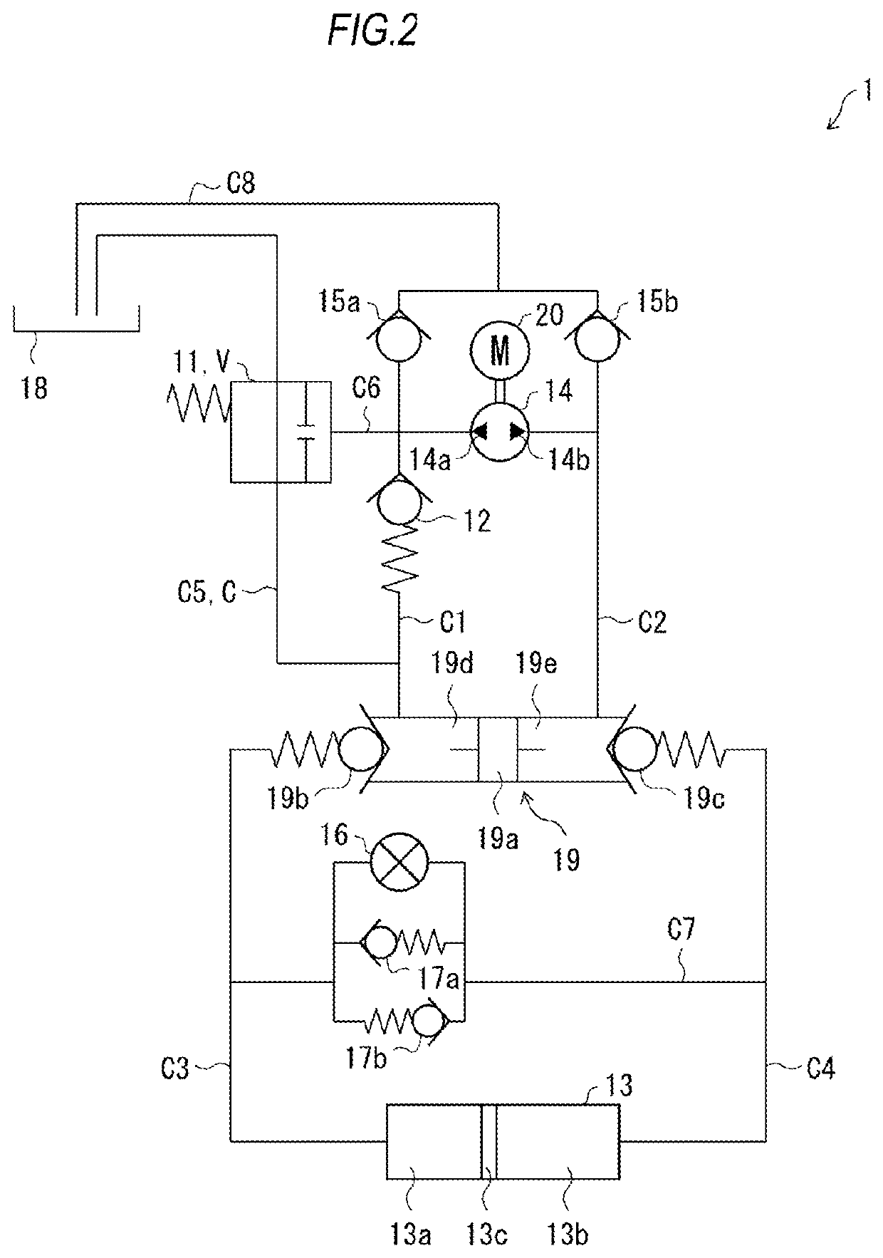
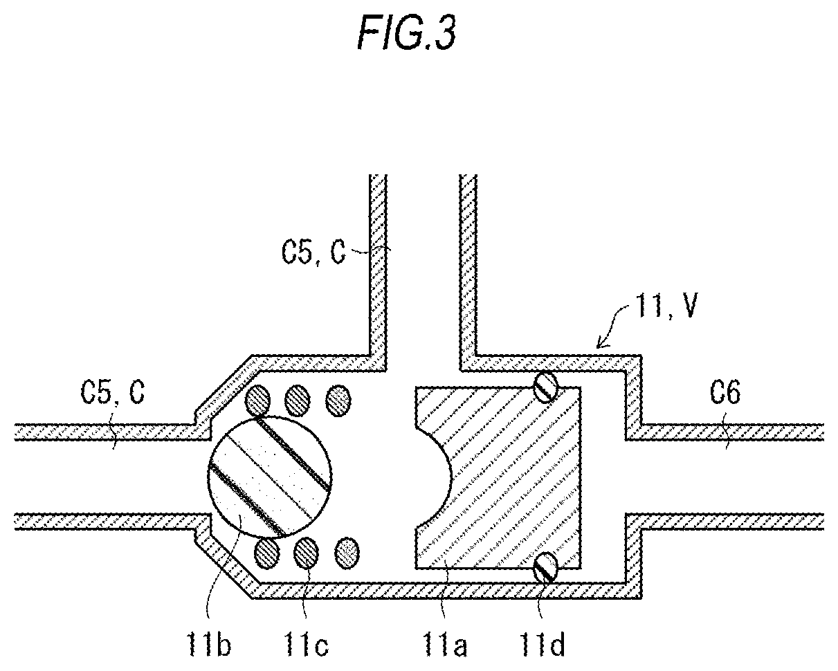
[0017]A steering device 1 according to Embodiment 1 will be described with reference to FIG. 1 to FIG. 3.

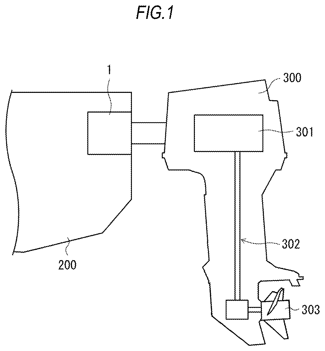
[0018]For example, the steering device according to the present embodiment is a watercraft steering device 1 (which will be hereinafter referred to “steering device 1” simply) used in order to swing an outboard motor left and right. As shown in FIG. 1, the steering device 1 is attached to a rear portion of a hull (body) 200 so as to be connected to an outboard motor 300. The outboard motor 300 is provided with an engine 301, a propeller 303, and a power transmission mechanism 302 which transmits motive power from the engine 301 to the propeller 303.

[0019]The steering device 1 swings the outboard motor 300 left and right so that the steering device 1 can control a travelling direction of the hull 200. More specifically, the outboard motor 300 is attached to be connected to a piston 13c of a cylinder 13 of the steering device 1 which will be described later. Due to the piston 13c m...

embodiment 2

[0062]A steering device 2 according to Embodiment 2 will be described with reference to FIG. 4 and FIG. 5.

[0063]FIG. 4 is a diagram showing an oil-hydraulic circuit of the steering device 2. The steering device 2 is configured to be further provided with a changeover valve 21, a check valve 22, an oil passage C9 and an oil passage C10 in addition to the respective constituents belonging to the aforementioned steering device 1. In the following description, members similar to or the same as the members which have been described above will be referred to by the same signs correspondingly and respectively, and description thereof will be omitted. In addition, the changeover valve 21 may be hereinafter referred to as second changeover valve, the check valve 22 may be hereinafter referred to as second check valve, and the oil passage C10 may be hereinafter referred to as sixth oil passage.

[0064]As shown in FIG. 4, the check valve 22 is provided on an oil passage C2. In addition, the oil ...

embodiment 3

[0087]A steering device 3 according to Embodiment 3 will be described with reference to FIG. 6 and FIG. 7.

[0088]FIG. 6 is a diagram showing an oil-hydraulic circuit of the steering device 3. The steering device 3 is configured to be provided with a changeover valve 23 and an oil passage C11 in place of the changeover valve 11 and the oil passage C6 of the aforementioned steering device 1. In the following description, members similar to or the same as the members which have been described above will be referred to by the same signs correspondingly and respectively, and description thereof will be omitted. In addition, the changeover valve 23 may be hereinafter referred to as third changeover valve, and the oil passage C11 may be hereinafter referred to as seventh oil passage.

[0089]As shown in FIG. 6, the oil passage C11 connects an oil passage C2 between a second shaft chamber 19e and a second discharge port 14b with the changeover valve 23. Incidentally, a similar technical idea to...


PUM


Abstract

A steering device includes: a cylinder; a normal / reverse rotation type hydraulic power source; an oil storage tank; a first oil passage that connects the cylinder with the hydraulic power source; a second oil passage that connects the cylinder with the hydraulic power source; an oil passage group that includes at least one oil passage connecting at least one of the first oil passage and the second oil passage with the oil storage tank; and a changeover valve group that performs changeover between a state in which hydraulic oil recovered from the cylinder flows back to the oil storage tank and a state in which hydraulic oil supplied from the hydraulic power source to the cylinder does not flow back to the oil storage tank, in accordance with a state of hydraulic oil supplied by the hydraulic power source.

Description

CROSS-REFERENCE TO RELATED APPLICATIONS[0001]This application is based upon and claims the benefit of priority to Japanese patent application No. 2019-091620, filed on May 14, 2019, the entire contents of which are incorporated herein by reference.TECHNICAL FIELD[0002]The present invention relates to a steering device and a watercraft steering device.BACKGROUND ART[0003]In the related art, steering devices are available and used in various fields. For example, a power tilt and power steering device provided with a power tilt hydraulic cylinder for tilting up / down an outboard motor body of an outboard motor and a power steering hydraulic cylinder swinging the outboard motor body of the outboard motor has been disclosed in JP-A-6-127475.[0004]The cylinder device having a configuration which uses a normal / reverse rotation type hydraulic power source is available in the related art. By use of the normal / reverse rotation type hydraulic power source, there is a merit that complication of ...

Claims


Application Information

Patent Timeline
IPC IPC(8): B63H20/00B63H25/30B63H20/12
CPCB63H20/12B63H25/30B63H21/265B63H5/125
Inventor TSUTSUI, HAYATO
Owner HITACHI ASTEMO LTD
Features
  • Generate Ideas
  • Intellectual Property
  • Life Sciences
  • Materials
  • Tech Scout
  • Unparalleled Data Quality
  • Higher Quality Content
  • 60% Fewer Hallucinations
Learn More