Cooling system for work machine

a cooling system and work machine technology, applied in the direction of machines/engines, fluid couplings, couplings, etc., can solve the problems of increasing the load imposed on the driving circuit, abnormal noise, increasing the cost of the system, etc., to reduce the discharge oil rate of the hydraulic pump, preventing the occurrence of peak pressure in the hydraulic circuit for driving the cooling fan, and reducing the effect of the increase of the load

Active Publication Date: 2005-08-25
KOMATSU LTD
View PDF6 Cites 45 Cited by
  • Summary
  • Abstract
  • Description
  • Claims
  • Application Information

AI Technical Summary

Benefits of technology

[0008] the system further comprising: (1) a variable displacement hydraulic pump driven by the engine; (2) a forwardly and reversely rotatable hydraulic motor operated by hydraulic oil discharged from the hydraulic pump; (3) a cooling fan driven by the hydraulic motor; (4) a selector valve for switching the rotating direction of the hydraulic motor between a forward direction and a reverse direction; and (5) controlling means for controlling switching of the selector valve and controlling the hydraulic pump so as to minimize the discharge oil rate of the hydraulic pump during switching of the selector valve.
[0009] According to the invention, the discharge oil rate of the hydraulic pump is controlled to be minimized in order to remove dust caught in the radiator when the selector valve is operated to change the rotating direction of the hydraulic motor from a forward direction to a reverse direction or vice versa. Therefore, occurrence of peak pressure in the hydraulic circuit for driving the cooling fan can be avoided, thereby restraining the increase of the load imposed on the hydraulic circuit and preventing occurrence of abnormal noise. In addition, since the discharge oil rate of the hydraulic pump can be restricted, a two position valve can be used as the selector valve, which leads to cost reduction. Further, since the discharge oil rate of the variable displacement hydraulic pump is properly controlled, waste of energy can be reduced compared to the system using a fixed displacement hydraulic pump, so that removal of dust from the radiator can be effectively carried out.
[0010] In the invention, the controlling means preferably controls the selector valve so as to change the rotating direction of the hydraulic motor from the forward direction to the reverse direction based on enumeration data from an operating time meter for counting the operating time of the work machine. With this arrangement, the operation of reversing the rotation of the hydraulic motor can be reliably carried out even if reversing interval is long. Further, the reverse rotation can be performed without use of an expensive special device, using an operating time meter that is usually equipped for ordinary work machines. This contributes to cost reduction.
[0011] The driving time of the hydraulic motor in the forward direction and the driving time of the hydraulic motor in the reverse direction are preferably settable by time setting means. With this arrangement, the forward and reverse rotation times can be set in compliance with the condition of the operation site where the work machine is used, which makes it possible to achieve a system enhanced in convenience.

Problems solved by technology

The above-described prior art systems have revealed the problem that the rotating direction of the cooling fan is sometimes switched while the cooling fan is rotating at high speed and this may cause a peak pressure in the fan driving circuit resulting in an increase in the load imposed on the driving circuit and occurrence of abnormal noise.
In addition, a switchover spool (selector valve) having a neutral position is necessary for changing the rotating direction of the cooling fan during high-speed rotation, which unavoidably entails an increase in the cost of the system.

Method used


Image

  • Cooling system for work machine
  • Cooling system for work machine
  • Cooling system for work machine

Examples


Embodiment Construction

[0017] Referring now to the accompanying drawings, a cooling system for a work machine will be concretely described according to a preferred embodiment of the invention.

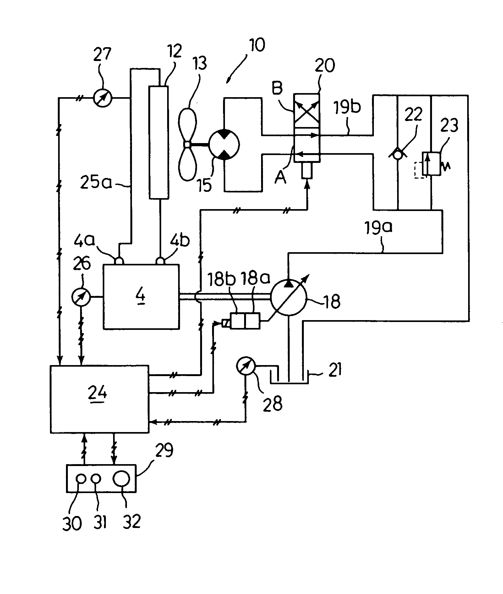
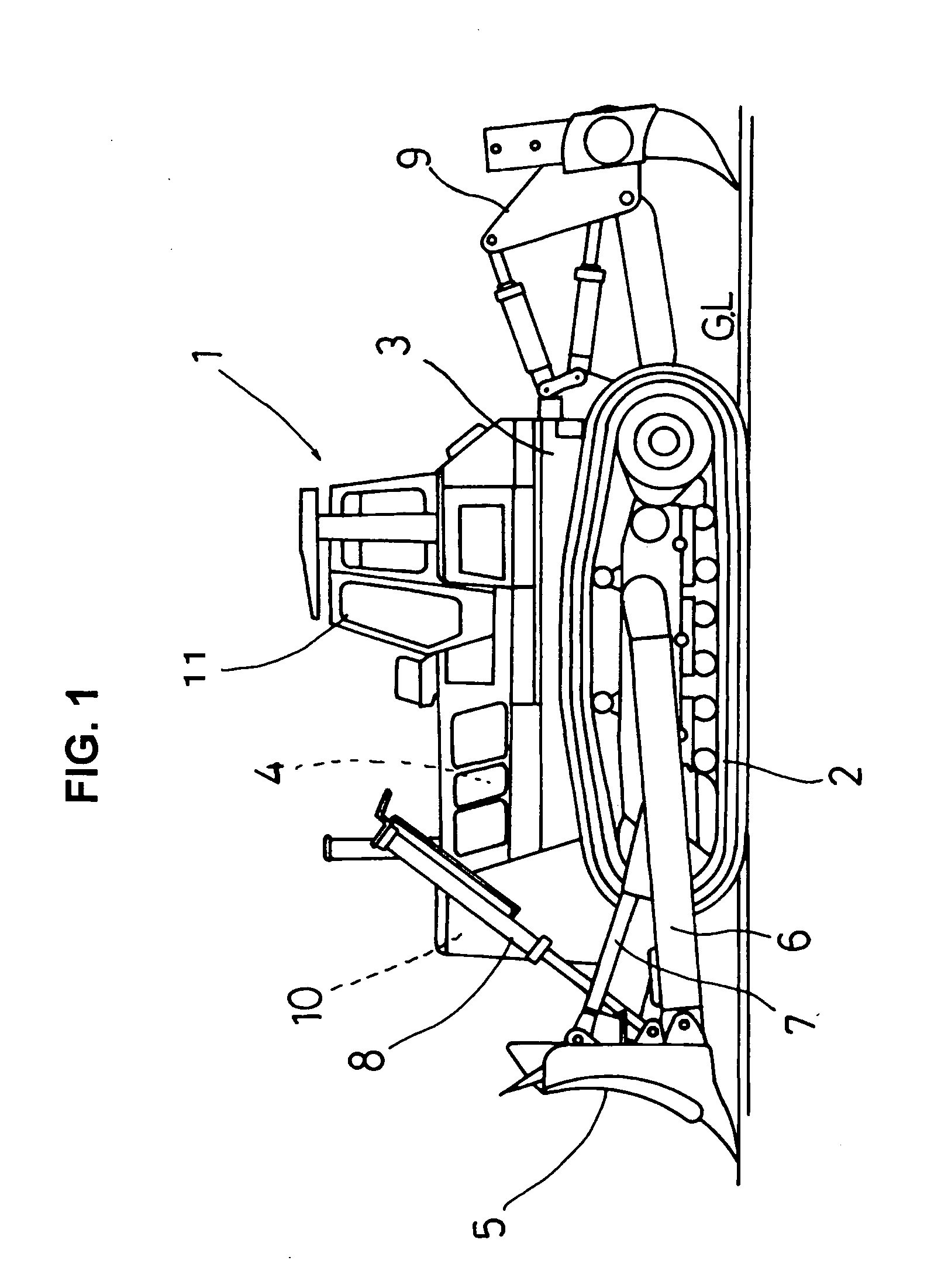
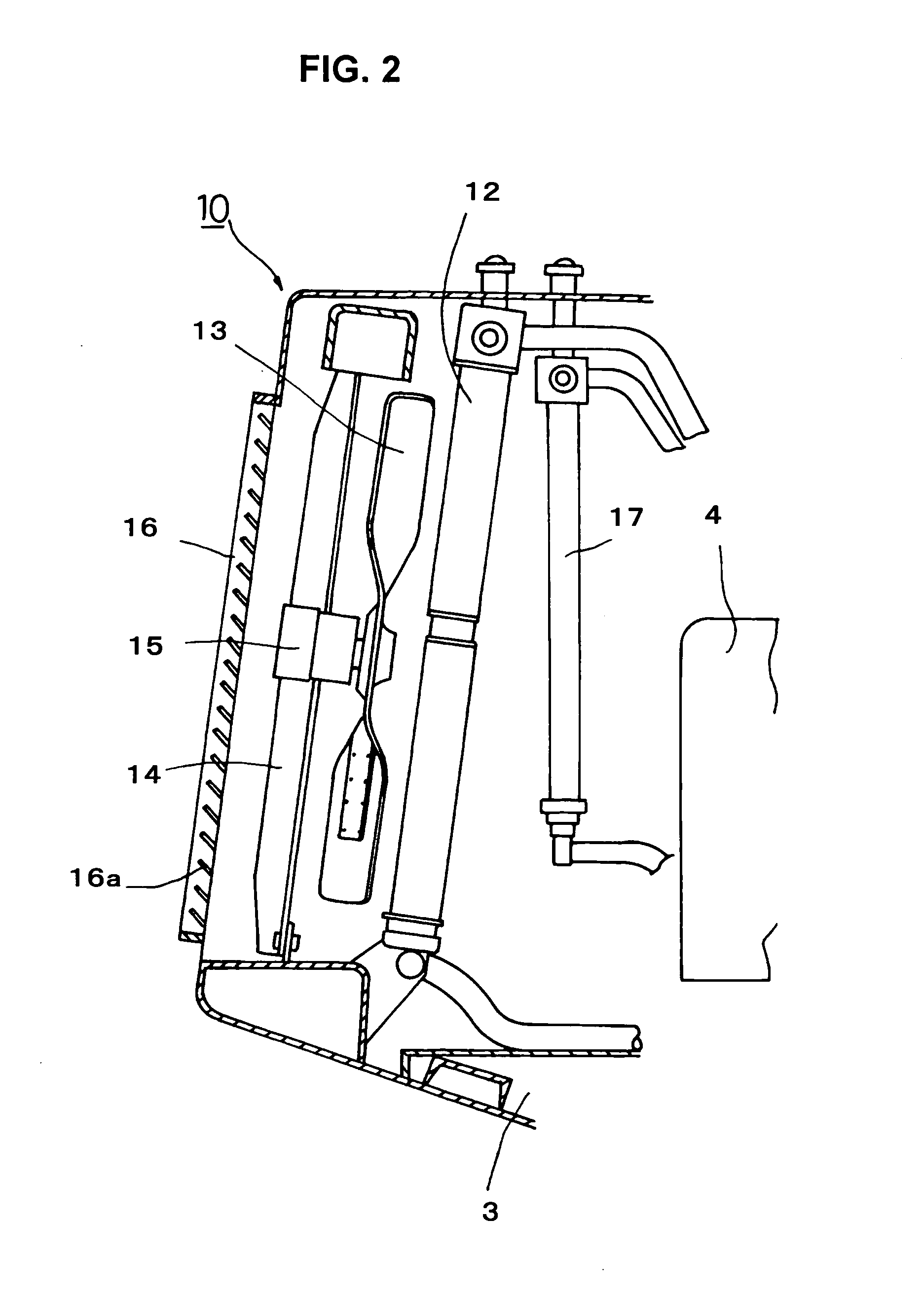
[0018]FIG. 1 shows a schematic side view of a bulldozer according to one embodiment of the invention. FIG. 2 is a schematic structural diagram of a cooling system incorporated in the bulldozer according to the embodiment.

[0019] In a bulldozer 1 of this embodiment, an engine 4 is mounted on an upper front part of a vehicle body 3 equipped with a track-type machine undercarriage 2 as shown in FIG. 1. Placed in front of the engine 4 is a cooling system 10 for cooling the engine 4. At a position in front of the vehicle body 3, a blade 5 is supported by frames 6 at its right and left sides so as to be operable by a tilt cylinder 7 and a lift cylinder 8. A ripper 9 is disposed behind the vehicle body 3 and an operator's cab 11 is provided at a central position slightly closer to the rear.

[0020] As shown in FIG. 2, the c...


PUM


Abstract

A cooling system for use in a work machine is provided, in which an increase in the load imposed on a fan driving circuit and occurrence of abnormal noise can be prevented without fail by means of an inexpensive arrangement at the time of switching the rotating direction of a cooling fan. To this end, the cooling system comprises: (1) a variable displacement hydraulic pump driven by the engine; (2) a forwardly and reversely rotatable hydraulic motor operated by hydraulic oil supplied from the hydraulic pump; (3) a cooling fan driven by the hydraulic motor; (4) an electromagnetic selector valve for switching the rotating direction of the hydraulic motor between a forward direction and a reverse direction; (5) controlling means for controlling switching of the electromagnetic selector valve and controlling the hydraulic pump so as to minimize the discharge oil rate of the hydraulic pump during switching of the electromagnetic selector valve.

Description

TECHNICAL FIELD [0001] The present invention relates to a cooling system for use in a work machine such as a bulldozer or hydraulic excavator, the system having a radiator for cooling a coolant for the engine and a cooling fan for forcibly cooling the radiator. BACKGROUND ART [0002] In typical cooling systems for cooling the engine or the like of a work machine, a cooling fan is driven by an electric or hydraulic motor and the rotational speed of the cooling fan is controlled independently of the control of the rotation of the engine. One example of such cooling systems is disclosed in Japanese Kokai Patent Publication No. 10-68142. [0003] As shown in FIG. 5, the cooling system disclosed in Japanese Kokai Patent Publication No. 10-68142 includes a radiator 52 and an oil cooler 53 which are disposed separately from an engine 51; a cooling fan 54 for forcibly cooling the radiator 52 and the oil cooler 53; and a fan driving circuit 55 for forwardly or reversely rotating the cooling fan...

Claims


Application Information

Patent Timeline
Patent Type & Authority Applications(United States)
IPC IPC(8): E02F9/00B60K11/04E02F9/08E02F9/22F01P5/04F01P7/04F01P7/10F01P11/12F16D31/02
CPCE02F9/0866E02F9/0875E02F9/2075E02F9/2235F16D2300/021E02F9/2292E02F9/2296F01P5/043E02F9/226
Inventor NAKAGAWA, TOMOHIROYAMAMOTO, SHIGERUKAMADO, MITSUHIKO
Owner KOMATSU LTD
Why Eureka
Try Eureka