
Method for non-destructive testing of walls of components

a technology of non-destructive testing and components, applied in the direction of material solid analysis using sonic/ultrasonic/infrasonic waves, measurement devices, etc., can solve the problems of inability to use permanent monitoring, inability to simultaneously measure wall thickness/wall erosion, and inability to use known sleeves for permanent monitoring. , to achieve the effect of reducing the number of cables and measuremen

Active Publication Date: 2020-11-19
FRAUNHOFER GESELLSCHAFT ZUR FOERDERUNG DER ANGEWANDTEN FORSCHUNG EV
View PDF0 Cites 0 Cited by
  • Summary
  • Abstract
  • Description
  • Claims
  • Application Information

AI Technical Summary

Benefits of technology

This patent invention allows for two measurement tasks to be performed at the same time using ultrasonic waves. This reduces the cost of equipment and measurement channels needed. The ultrasonic transducers can be optimized for each task by selecting the best emission ratio between them or adapting the types of waves used. For longer travel paths and smaller components, higher powers and amplitudes can be used with horizontally polarized transverse waves than with vertically polarized waves.

Problems solved by technology

For the applications considered here, this damage is cracks, corrosion phenomena, wall erosion, pitting, holes and delamination.
For non-destructive testing measurements, a number of shear wave testing systems are available but currently cannot be used for permanent monitoring (the measurement system remains on the component).
However, these known sleeves are not simultaneously used for a wall thickness measurement / wall erosion measurement.

Method used


Image

  • Method for  non-destructive testing of walls  of components
  • Method for  non-destructive testing of walls  of components
  • Method for  non-destructive testing of walls  of components

Examples


Embodiment Construction

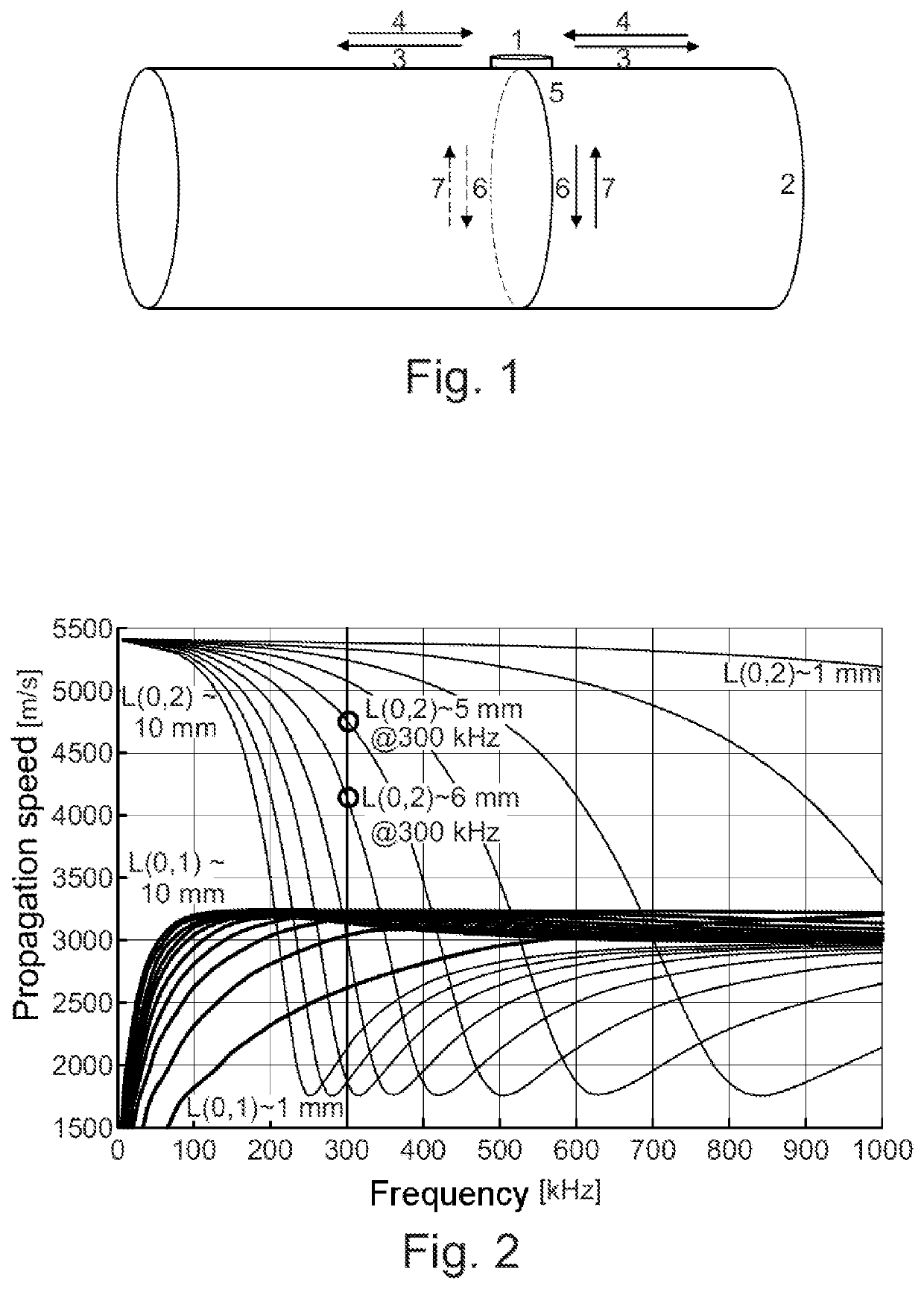
[0032]FIG. 1 shows a measurement setup which can be used to carry out the method, with the measurement principle.

[0033]In this case, an ultrasonic transducer 1 is fixed to an outer lateral surface of a pipe as a component 2. The ultrasonic transducer 1 is connected to an electrical voltage source (not shown) and is operated with an electrical AC voltage at a predefined frequency, with the result that ultrasonic waves are emitted by said transducer. In addition, in this embodiment, the transducer is connected to an electronic evaluation unit (not shown) which is designed to evaluate ultrasonic waves 3, 4, 6 and 7 detected using the ultrasonic transducer 1, which relates, in particular, to their amplitude and / or travel time.

[0034]During the emission of ultrasonic waves, laterally emitted horizontally polarized transverse waves 3 are emitted once and propagate in the wall of the pipe 2, which is indicated with arrows. Said waves can be used for the non-destructive testing of defects, f...


PUM

PropertyMeasurementUnit
frequencyaaaaaaaaaa
frequencyaaaaaaaaaa
thicknessaaaaaaaaaa

Abstract

A method for non-destructive testing of walls of components, at least one ultrasonic transducer (1) which is fixed to a surface of the wall is used to emit horizontally polarized transverse waves (3) in a lateral propagation direction and compression waves or vertically polarized transverse waves (6) in a radial propagation direction. The at least one ultrasonic transducer (1) and / or at least one further ultrasonic transducer arranged at a known distance from the at least one ultrasonic transducer (1) on the respective wall of the component (2) is / are used to detect horizontally polarized transverse waves (4) reflected by defects and compression waves or vertically polarized transverse waves (7) after or while running the non-destructive testing of the wall in order to determine the respective wall thickness.

Description

BACKGROUND OF THE INVENTION[0001]The invention relates to a method for the non-destructive testing of walls running around the periphery of components. It can be used, in particular, to test pipes, internally hollow containers, rotor blades, aircraft wings and other components preferably having a closed geometry. The wall of the components may be composed of different materials, in particular steel.[0002]Infrastructure must be regularly tested for damage if it is critical. This is stipulated in policies. For the applications considered here, this damage is cracks, corrosion phenomena, wall erosion, pitting, holes and delamination. These must be able to be reliably detected as of a relevant size in order to ensure the safety of the infrastructure.[0003]In practice, there are various possibilities both for a non-destructive test and for permanent monitoring (sensors and actuators remain on the component). Ultrasonic testing, thermography, eddy current methods, radiography, visual insp...

Claims


Application Information

Patent Timeline
Patent Type & Authority Applications(United States)
IPC IPC(8): G01B17/02G01N29/07G01N29/22G01N29/24
CPCG01N29/245G01N29/07G01B17/02G01N2291/0289G01N2291/2634G01N2291/011G01N2291/02854G01N2291/0234G01N2291/101G01N29/223G01N29/043G01N2291/0422G01N29/11G01N2291/0421G01N2291/0258G01N2291/044
Inventor WEIHNACHT, BIANCAGAUL, TOBIASLIESKE, UWESCHUBERT, LARS
Owner FRAUNHOFER GESELLSCHAFT ZUR FOERDERUNG DER ANGEWANDTEN FORSCHUNG EV
Learn More