Method for processing uplink control information and terminal

a control information and terminal technology, applied in the field of communication technology, can solve the problems of unprecedented challenges in the future mobile communication technology, no effective method for how the uci is determined, and difficult for the base station to adjust the pusch resources, so as to achieve effective transmission and improve transmission efficiency.

Active Publication Date: 2020-11-19
SAMSUNG ELECTRONICS CO LTD
View PDF2 Cites 15 Cited by
  • Summary
  • Abstract
  • Description
  • Claims
  • Application Information

AI Technical Summary

Benefits of technology

[0091]In the present disclosure, by determining the UCI which overlaps with a PUSCH resource in time domain according to the PUSCH resource, the determination of the UCI to be transmitted is achieved; then by determining whether to transmit the UCI and performing corresponding processing based on the determination result, effective transmission of the UCI to be transmitted is achieved, and transmission efficiency is improved.
[0092]Additional aspects and advantages of the invention will be set forth in part in the description which follows and in part will become apparent from the description, or may be learned by practice of the invention.

Problems solved by technology

The rapid development of information industry, particularly the increasing demand from the mobile Internet and the Internet of Things (IoT), brings about unprecedented challenges in the future mobile communications technology.
However, there is no effective method for how the UCI determined when the user terminal has started to prepare the PUSCH is appended to the PUSCH for transmission.
In addition, since the resources for GF uplink transmission are semi-statically configured and the base station may not be able to decide whether the user terminal should transmit the uplink data, it is difficult for the base station to adjust the PUSCH resources according to the UCI and the uplink data to be transmitted.

Method used


Image

  • Method for processing uplink control information and terminal
  • Method for processing uplink control information and terminal
  • Method for processing uplink control information and terminal

Examples


embodiment 1

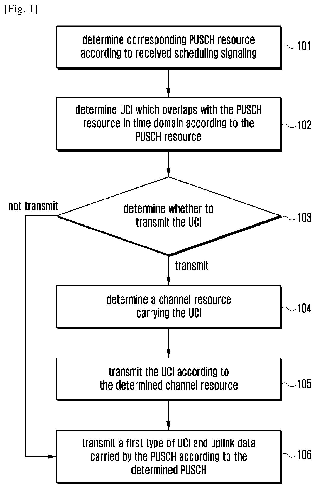
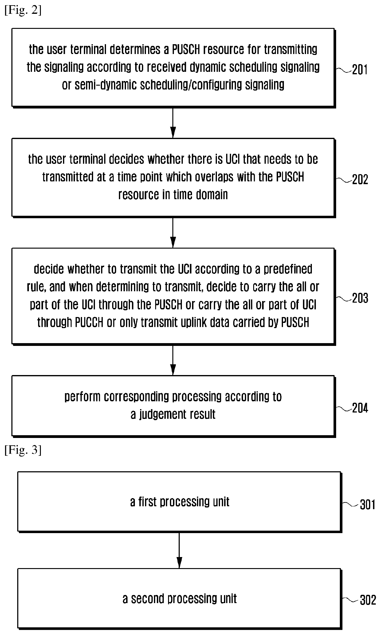
[0202]If the slot n is an uplink slot for uplink transmission that is configured by the base station, and the user terminal has uplink data that needs to be transmitted in the slot n, then the user terminal needs to decide whether there is UCI that may need to be transmitted in the slot n. If there is the UCI, the user terminal decides to transmit the PUSCH carrying the uplink data in the slot n according to a predefined rule and transmits all or part of the UCI at the same time on the PUSCH; or only the PUSCH carrying the uplink data is transmitted in slot n, and the PUSCH does not carry the UCI; or only the PUCCH carrying the UCI is transmitted in slot n, and the PUSCH for carrying at least uplink data is not transmitted.

[0203]The PUSCH may be a GF PUSCH, or may be a PUSCH scheduled based on a dynamic UL grant.

[0204]The transmitting the PUSCH in the slot n may include at least one of the following two situations: in the slot n, the PUSCH is transmitted according to a configured GF...

embodiment 2

[0308]If the slot n is an uplink slot configured by the base station and available for GF uplink transmission, and the user terminal has uplink data that needs to be transmitted in slot n, then the user terminal needs to decide whether there is UCI that may need to be transmitted in slot n. If there is the UCI, the user terminal decides it is the uplink data carried by the PUSCH for transmitting the GF in slot n and transmits all or part of UCI on the PUSCH at the same time, or only transmits the uplink data carried by the PUSCH in slot n without transmitting the UCI; or only transmits the UCI carried by the PUCCH in slot n without transmitting the PUSCH carrying at least the uplink data.

[0309]The predefined rule is to determine whether all or part of UCI may be transmitted on the PUSCH according to the predefined threshold and / or the priority.

[0310]Wherein, the predefined priority includes at least one of the following:

[0311](2.1) The predefined priority is predefined by the standa...

embodiment 3

[0335]The ACK / NACK is transmitted on the PUSCH of the GF. When the number of bits of the ACK / NACK exceeds the predefined threshold, the rate matching needs to be performed on the PUSCH. In order to ensure that the base station side and the user side have the same understanding of the rate-matching resources, it is necessary to make the user terminal and the base station side have the same understanding about the number of bits of the ACK / NACK.

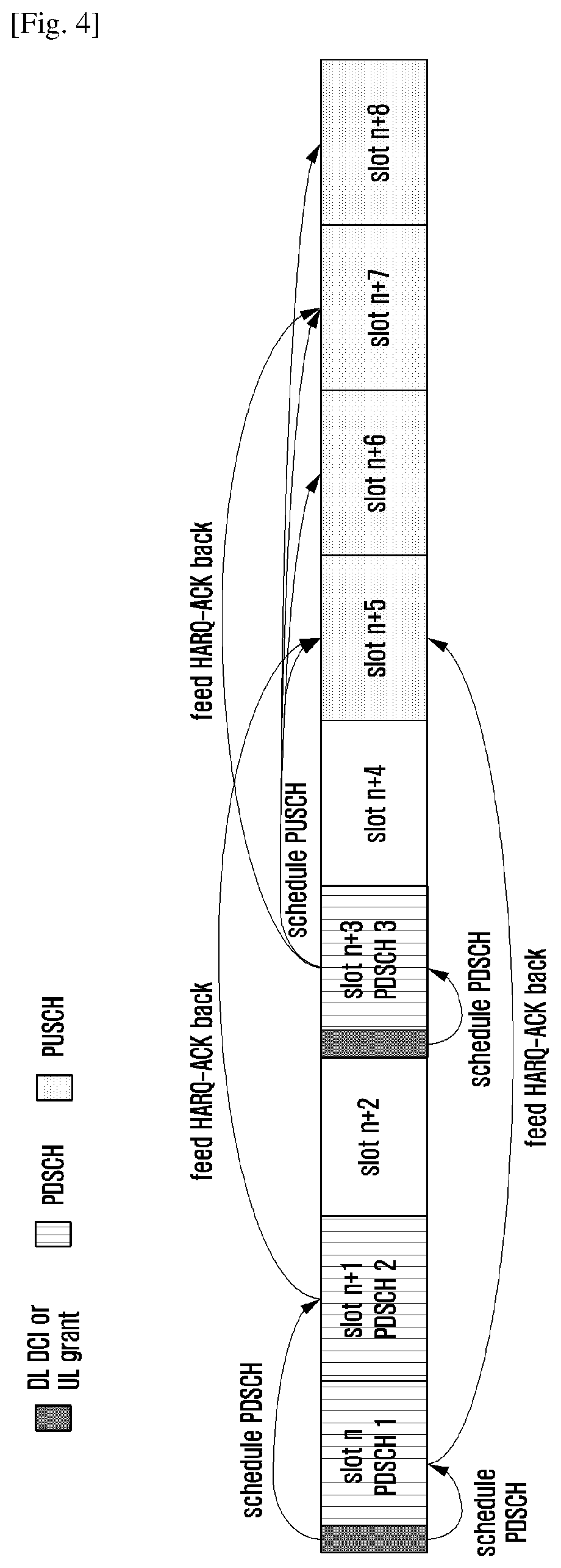
[0336]Different from the scheduling-based PUSCH, the number of bits of the ACK / NACK may be explicitly indicated in the dynamic UL grant of the scheduling-based PUSCH, and the PUSCH of the GF does not have the UL grant, and therefore the number of bits of the ACK / NACK may only be determined according to the predefined rule and the scheduling signaling of the PDSCH.

[0337]In an implementation, the number of bits of ACK / NACK bits transmitted on the PUSCH of the GF is always an integral multiple of M. Correspondingly, if the base station finds that ...


PUM


Abstract

The present disclosure relates to a communication method and system for converging a 5th-Generation (5G) communication system for supporting higher data rates beyond a 4th-Generation (4G) system with a technology for Internet of Things (IoT). The present disclosure may be applied to intelligent services based on the 5G communication technology and the IoT-related technology, such as smart home, smart building, smart city, smart car, connected car, health care, digital education, smart retail, security and safety services. The present disclosure provides a method for processing uplink control inforamtion (UCI) and a terminal. The method for processing UCI includes: determining the UCI which overlaps with a Physical Uplink Shared Channel (PUSCH) resource in time domain according to the PUSCH resource; determining whether to transmit the UCI, and performing corresponding processing based on a determination result. The present disclosure realizes effective transmission of UCI to be transmitted, and improves transmission efficiency.

Description

TECHNICAL FIELD[0001]The present disclosure relates to the field of communications technology, and in particular, to a method for processing uplink control information and a terminal.BACKGROUND ART[0002]To meet the demand for wireless data traffic having increased since deployment of 4G communication systems, efforts have been made to develop an improved 5G or pre-5G communication system. Therefore, the 5G or pre-5G communication system is also called a ‘Beyond 4G Network’ or a ‘Post LTE System’. The 5G communication system is considered to be implemented in higher frequency (mmWave) bands, e.g., 60 GHz bands, so as to accomplish higher data rates. To decrease propagation loss of the radio waves and increase the transmission distance, the beamforming, massive multiple-input multiple-output (MIMO), Full Dimensional MIMO (FD-MIMO), array antenna, an analog beam forming, large scale antenna techniques are discussed in 5G communication systems. In addition, in 5G communication systems, ...

Claims


Application Information

Patent Timeline
Patent Type & Authority Applications(United States)
IPC IPC(8): H04W72/12H04L1/18H04L5/00H04W76/27H04W72/04
CPCH04W72/0413H04W76/27H04W72/1242H04L5/0055H04W72/042H04L1/1819H04W72/1268H04L1/1671H04L1/1854H04L5/0007H04L5/0051H04L5/0053H04L1/1864H04W72/569H04L5/0048H04W72/0446H04W72/21H04W72/23
Inventor WANG, YIZHANG, SHICHANGLI, YINGYANG
Owner SAMSUNG ELECTRONICS CO LTD
Why Eureka
Try Eureka